Length & Spacing Welded Nozzles
Minimum Length and Spacing without Reninforcement
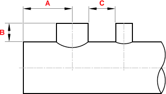
| NPS of Nozzle |
Center of Nozzle to End of Run A |
O.D. of Run to End of Nozzle B |
O.D. to O.D. of Nozzle C |
| 2.1/2 | 114 | 76 | 76 |
| 3 | 127 | 89 | 89 |
| 4 | 152 | 102 | 102 |
| 5 | 178 | 114 | 114 |
| 6 | 203 | 127 | 127 |
| 8 | 254 | 152 | 152 |
| 10 | 305 | 178 | 178 |
| 12 | 356 | 203 | 203 |
| 14 | 381 | 216 | 216 |
| 16 | 432 | 229 | 229 |
| 18 | 483 | 254 | 254 |
| 20 | 533 | 279 | 279 |
| 24 | 610 | 305 | 305 |
| Table 1 - 3 | |||
Minimum Length and Spacing with Reninforcement
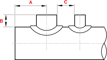
| NPS of Nozzle |
Center of Nozzle to End of Run A |
O.D. of Run to End of Nozzle B |
O.D. to O.D. of Nozzle C |
| 2.1/2 | 152 | 114 | 152 |
| 3 | 178 | 127 | 178 |
| 4 | 203 | 140 | 203 |
| 5 | 241 | 152 | 241 |
| 6 | 279 | 165 | 279 |
| 8 | 356 | 203 | 356 |
| 10 | 432 | 241 | 432 |
| 12 | 508 | 279 | 508 |
| 14 | 559 | 305 | 559 |
| 16 | 635 | 330 | 635 |
| 18 | 711 | 356 | 711 |
| 20 | 787 | 381 | 787 |
| 24 | 914 | 406 | 914 |
| Table 2 - 3 | |||
Minimum Length and Spacing Integrally Reinforced
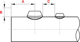
| NPS of Nozzle |
Center of Nozzle to End of Run A |
O.D. of Run to End of Nozzle B |
O.D. to O.D. of Nozzle C |
| 2.1/2 | 140 | MFR Standard |
76 |
| 3 | 152 | 76 | |
| 4 | 178 | 89 | |
| 5 | 203 | 102 | |
| 6 | 254 | 127 | |
| 8 | 305 | 152 | |
| 10 | 356 | 178 | |
| 12 | 406 | 216 | |
| 14 | 432 | 229 | |
| 16 | 483 | 254 | |
| 18 | 533 | 279 | |
| 20 | 584 | 305 | |
| 24 | 660 | 356 | |
| Table 3 - 3 | |||
Notes..
- MFR = Manufacturer
- All nozzle welds should be checked for compliance with the applicable code requirements.
- It is preferred that multiple branch openings of in-line nozzles be spaced so that their reinforcement zones do not overlap. If closer specing is necessary, the reinforcement requirements of the applicable construction code shall be met.
- Some configurations of integrally reinforced nozzles in combination with certain header sizes may present a problem in the radiographic examination of the attachment weld due to inability to meet the geometric unsharpness requirements of the construction code.
- Where attachments such as flanges, fittings valve and pipe insulation are involved, minimum dimensions tabulated may have to be increased to allow for required clearances.
- In special cases, it may be possible to reduce the dimensions given in the tables. Such design should then be submitted to the fabricator for individual considerations, as close spacing may involve additional shop operation to prevent, or correct distortion.
- Integrally reinforced nozzles are considered to be the commercially available types.
- In cases of different nozzle diameters, dimension C, should be determinded on the basis of the larger of the two of adjacted nozzles.
Certain materials and combinations of nozzle and header pipe size and wall thickness together with multiple branch openings welded to a header may result in distortion of the header pipe.