Dimensions Weld Neck & Slip-On flanges BS 3293 Class 400
| NPS | O | B1 | C | Y2/Y1 | A | X1 |
| 26 | 971.5 | 666.7 | 88.9 | 193.7 | 668.3 | 693.7 |
| 28 | 1035.0 | 717.6 | 95.2 | 206.4 | 719.1 | 746.1 |
| 30 | 1092.2 | 768.3 | 101.6 | 219.1 | 769.6 | 800.1 |
| 32 | 1149.3 | 819.1 | 107.9 | 231.8 | 822.3 | 852.5 |
| 34 | 1206.5 | 869.9 | 111.1 | 241.3 | 873.1 | 904.9 |
| 36 | 1270.0 | 920.7 | 114.3 | 250.8 | 925.5 | 958.8 |
| NPS | X | R | NBH | DBH | D | r |
| 26 | 727.1 | 749.3 | 28 | 47.6 | 876.3 | 11.11 |
| 28 | 782.6 | 800.1 | 28 | 50.8 | 939.8 | 12.7 |
| 30 | 836.6 | 857.2 | 28 | 54.0 | 996.9 | 12.7 |
| 32 | 889.0 | 914.4 | 28 | 54.0 | 1054.1 | 12.7 |
| 34 | 944.6 | 965.2 | 28 | 54.0 | 1104.9 | 14.29 |
| 36 | 1012.9 | 1022.3 | 32 | 54.0 | 1168.4 | 14.29 |
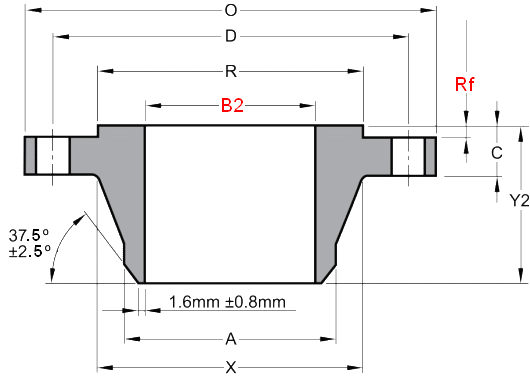
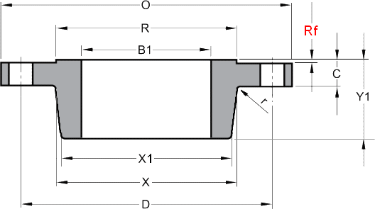
Indications..
- NPS = Nominal Pipe Size
- O = Outside Diameter of Flange
- B1 = Flange Bore Slip-On
- C = Thickness of Flange Min
- Y2/Y1 = Weld Neck / Slip-On Overall Length
- A = Weld Neck Diameter at Weld Bevel
- X1 = Slip on Hub Diamameter at Small End
- X = Weld Neck / Slip-On Hub Diameter
- R = Raised Face (O.D.) Outside Diameter
- NBH = Number of Bolt Holes
- DBH = Diameter of Bolt Holes
- r = Fillet Radius
- D = Diameter of Bolt Circle
- B2 = To be specified by purchaser
- Rf = Class 150-300 Rf height 1.6mm
Class 400-600 Rf height 6.35mm
Weights of Class 400 Weld Neck & Slip-On flanges
| NPS | Weld Neck kg |
Slip-On kg |
| 26 | 340 | 295 |
| 28 | 399 | 354 |
| 30 | 454 | 408 |
| 32 | 522 | 465 |
| 34 | 590 | 522 |
| 36 | 669 | 601 |
Note..
- Weights are based on manufacturer's data and are approximate
Ring Joint Facings BS 3293
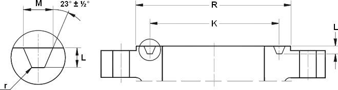
| NPS | Ring No. |
Raised Face O.D. |
Groove | Weights in Kg Weld Neck Slip-On |
||||
| R | K | L | M | Cl 300 |
Cl 400 |
Cl 600 |
||
| 26 | R93 | 809.6 | 749.3 | 12.7 | 19.8 | 298 270 |
349 304 |
446 417 |
| 28 | R94 | 860.4 | 800.1 | 12.7 | 19.8 | 360 333 |
409 364 |
518 482 |
| 30 | R95 | 917.6 | 857.2 | 12.7 | 19.8 | 412 376 |
465 419 |
570 537 |
| 32 | R96 | 984.2 | 914.4 | 14.3 | 23.0 | 465 425 |
539 482 |
697 622 |
| 34 | R97 | 1035.0 | 965.2 | 14.3 | 23.0 | 536 492 |
608 540 |
735 670 |
| 36 | R98 | 1092.2 | 1022.3 | 14.3 | 23.0 | 595 548 |
689 621 |
800 764 |
Indications..
- NPS = Nominal Pipe Size
- R = Raised Face (O.D.) Outside Diameter
- K = Pitch Diameter
- L = Groove Depth
- M = Groove Width
- r = Corner radius at bottom of groove 1.6 mm max
Dimensions and Tolerances BS 3293
| TYPE OF FLANGES | INDICATIONS | TOL |
| Weld Neck and Slip-On flanges | Raised face diameter | ±0.40 |
| Flange thickness | +4.76 -0 |
|
| Overall length | ±3.18 | |
| Outside diameter at welding end of weld neck hub | +3.97 -0.79 |
|
| Inside diameter of weld neck flange | +3.18 -1.59 |
|
| Inside diameter of slip on flange | +1.59 -0 |
|
| Ring Joint Facing on Weld Neck and Slip-On flanges | Depth of groove | +0.40 -0 |
| Width of groove | ±0.20 | |
| Pitch diameter of groove | ±0.13 | |
General note..
- All dimensions above are in millimeters unless otherwise indicated.