Pipe Flow Measurement.. Venturi Flow Meter
Why measure Flow?
In many of today's industrial processes, it is essential to measure accurately the rate of fluid flow within a system as a whole or in part. This applies equally to gases and liquids (e.g. carbon dioxide, nitrogen, liquors etc.) which are an integral part of the process, or to compressed air, water or steam which are fundamental to plant operation. The installation of any flowmeter can be justified in one of two ways..
1. Process control
Here the flowmeter is used to measure the rate of fluid or energy flow to allow the process to be controlled and so ensure that the end product is of the required quality. A common example of this would be in steam injection systems for the animal feeds industry...too much steam and the product will not pellet...too little steam and the raw materials will not process and may damage the production machinery.
2. Cost allocation
Where energy is used to provide process or space heating, it is fundamental to know where the costs associated with the energy are actually being incurred. Flowmetering allows energy costs to be allocated to a particular product, department or other user this usually resulting in a significant reduction in total energy costs.
Understanding Pipe Flow Rate
The term pipe flow rate is often used to refer to flow rate for any closed conduit flow under pressure. The closed conduit is often circular, but may also be square or rectangular, such as a heating duct. The other major category of flow is open channel flow, which occurs when there is a free liquid surface open to atmospheric pressure.
Measurement of the flow rate of a fluid flowing under pressure is carried out for a variety of purposes, such as billing for water supply to homes or businesses, or for monitoring or process control of a wide variety of industrial processes which involve flowing fluids.
Pipe flow measurement is often done with a differential pressure flow meter like the orifice, flow nozzle, and ventruri meter; Venturi Meters are discussed in this article.
For each type, a constriction in the flow path causes a pressure drop across the meter. The pressure drop can be measured and correlated with flow rate.
The Venturi Principle and Bernoulli's Equation
The differential producing flowmeter or Venturi has a long history of uses in many applications. Due to its simplicity and dependability, the Venturi is among the most common flowmeters. With no moving parts or abrupt flow restrictions, the Venturi can measure fluid flowrates with a minimal total pressure loss.
The principle behind the operation of the Venturi flowmeter is the Bernoulli effect. The Venturi measures a fluid's flowrate by reducing the cross sectional flow area in the flow path and generating a pressure difference. After the pressure difference is generated, the fluid is passed through a pressure recovery exit section where up to 80% of the differential pressure generated at the throat is recovered.

Daniel Bernoulli
Bernoulli's Equation
The Venturi Principle
Increase in fluid speed results in decrease in internal pressure.
In the image above, the fluid, either liquid or gaseous, enters the Venturi at the location with a cross-sectional area A1, pressure P1, and velocity v1. These properties form the potential and kinetic energy of the fluid at one location. Energy is conserved in a closed system, that is, the sum of potential and kinetic energy at one location must equal the sum of the potential and kinetic energy at any another location in the system.
If potential energy decreases at one location, the kinetic energy must proportionally increase at that location. The fluid now enters the throat of the Venturi with a new area A2, which is smaller than A1. In a closed system mass can be neither created nor destroyed (law of conservation of mass, simply, what goes in, must come out), and as such, the volumetric flowrate at area A1 must equal the volumetric flowrate at area A2.
If the area at location A2 is smaller than A1, the fluid must travel faster to maintain the same volumetric flowrate. This increase in velocity results in a decrease in pressure which follows Bernoulli's equation. The result.. by knowing the pressure and cross-sectional area at two locations, one can calculate the velocity of the fluid. With the velocity of the fluid and its density, one can calculate the flowrate.
A Venturi requires two pressure and one temperature measurement to accurately determine flow. The first pressure is measured at the Venturi's upstream location, P1. This is used for the density calculation and the high side input to the differential pressure measurement.
Venturi Meters
The principle of this flow measurement device was first documented by J.B. Venturi in 1797 in Italy. The principle under which these devices operate is that some pressure head is converted velocity head when the cross-sectional area of flow decreases (Bernoulli equation).
Thus, the head differential can be measured between the upstream section and the throat section to give an estimation of flow velocity, and this can be multiplied by flow area to arrive at a discharge value. The converging section is usually about 21°, and the diverging section is usually from 5° to 7°.
Venturi Flow Meter
A form of the calibration equation is
Where C is a dimensionless coefficient from approximately 0.935 (small throat velocity and diameter) to 0.988 (large throat velocity and diameter); β is the ratio of D2 / D1; D1 & D2 are the inside diameters at the upstream and throat sections, respectively; A2 is the area of the throat section; Δh is the head differential; and "sg" is the specific gravity of the manometer liquid.
The discharge coefficient, C, is a constant value for given venturi dimensions. Note that if D2 = D1, then β = 1, and Q is undefined; if D2 > D1, you get the square root of a negative number (but neither condition applies to a venturi). The coefficient, C must be adjuste to accommodate variations in water temperature. The value of β is usually between 0.25 and 0.50, but may be as high as 0.75.
Straightening vanes may be required upstream of the venturi to prevent swirling flow, which can significantly affect the calibration. It is generally recommended that there should be a distance of at least 10xD1 of straight pipe upstream of the venturi.
The head loss across a venturi meter is usually between 10% and 20% of Δh. This percentage decreases for larger venturis and as the flow rate increases. Venturi discharge measurement error is often within ±0.5% to ±1% of the true flow rate value.
Venturi meters have been made out of steel, iron, concrete, wood, plastic, brass, bronze, and other materials and many commercial venturi meters have patented features.
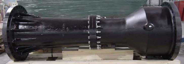
Flanged Venturi Flow Meter
Standards for Flow Nozzles, Venturies and Orifices
ISO 5167-3:2003 specifies the geometry and method of use (installation and operating conditions) of nozzles and Venturi nozzles when they are inserted in a conduit running full to determine the flow-rate of the fluid flowing in the conduit.
ISO 5167-3:2003 also provides background information for calculating the flow-rate and is applicable in conjunction with the requirements given in ISO 5167-1.
ISO 5167-3:2003 is applicable to nozzles and Venturi nozzles in which the flow remains subsonic throughout the measuring section and where the fluid can be considered as single-phase. In addition, each of the devices can only be used within specified limits of pipe size and Reynolds number. It is not applicable to the measurement of pulsating flow. It does not cover the use of nozzles and Venturi nozzles in pipe sizes less than 50 mm or more than 630 mm, or for pipe Reynolds numbers below 10000.
ISO 5167-3:2003 deals with two types of standard nozzles, the ISA 1932 nozzle and the long radius nozzle, as well as the Venturi nozzle.
The two types of standard nozzle are fundamentally different and are described separately in ISO 5167-3:2003. The Venturi nozzle has the same upstream face as the ISA 1932 nozzle, but has a divergent section and, therefore, a different location for the downstream pressure tappings, and is described separately. This design has a lower pressure loss than a similar nozzle.
For both of these nozzles and for the Venturi nozzle direct calibration experiments have been made, sufficient in number, spread and quality to enable coherent systems of application to be based on their results and coefficients to be given with certain predictable limits of uncertainty.
BS 1042-1-1.2 standard specifies the measurement of fluid flow in closed conduits. Pressure differential devices. Specification for square-edged orifice plates and nozzles (with drain holes, in pipes below 50 mm diameter, as inlet and outlet devices) and other orifice plates.
Geometry and method of use for conical entrance orifice plates, quarter circle orifice plates and eccentric orifices plates. Also square-edged orifice plates and nozzles outside the scope of BS 1042:Section 1.1.
ASME MFC-3M standard specifies the geometry and method of use (installation and flowing conditions) for orifice plates, nozzles, and Venturi tubes when they are inserted in a conduit running full, to determine the rate of the fluid flowing. It also gives necessary information for calculating flow rate and its associated uncertainty.
It applies only to pressure difference devices in which the flow remains turbulent and subsonic throughout the measuring section is steady or varies only slowly with time and the fluid is considered single-phased. In addition, the uncertainties are given in the appropriate sections of this Standard for each of these devices, within the pipe size and Reynolds number limits which are specified.
It deals with devices for which sufficient calibrations have been made to enable the specification of coherent systems of application and to enable calculations to be made with certain predictable limits of uncertainty. The devices introduced into the pipe are called primary devices. The term primary device also includes the pressure taps and the associated upstream and downstream piping.
All other instruments or devices required for the measurement or transmission of the differential pressures are known as secondary elements, and in combination are referred to as the secondary devices. This Standard covers the primary devices; secondary devices will be mentioned only occasionally.
The following primary devices are covered in this Standard.. (a) orifice plates, which can be used with the following arrangements of pressure taps.. (1) flange pressure taps, (2) D and D/2 pressure taps, (3) corner pressure taps. (b) nozzles.. (1) ASME long radius nozzles. (c) Venturi tubes.. (1) classical Venturi tubes.
This Standard does not pipe or conduit sizes under 50 mm (2 in.) nominal.
This Standard does not apply to ASME Performance Test Code measurements.
The Standard is applicable to measurement of flow of any fluid, (liquid, vapor, or gas).
References..
- Spirax-Sarco
- Miller, R.W.. Flow measurement engineering handbook. 3rd Ed. McGraw-Hill Book Co., New York, N.Y.
- USBR. Flow measurement manual. Water resource(s) Publications, LLC. Highlands Ranch, CO.
Remark(s) of the Author...
Baron Kelvin (William Thomson) once said..
"When you can measure what you are speaking about and express it in numbers, you know something about it; but when you cannot measure it, when you cannot express it in numbers, your knowledge is of a meagre and unsatisfactory kind."
Baron Kelvin
In other words, you cannot manage what you cannot measure and nowhere is that more true than in the measurement of flow.