Valve Interlock System
A valve interlock is a trapped key lock assembly which locks the valve in one or two positions - open and/or closed - with one key trapped within the lock assembly and one key free. It's about controlling the sequence of events, conducting different valve process activities.
To change the valve position (open-to-close or close-to-open), two keys need to be inserted into the lock assembly. The free key can only be released when the valve is in the open or closed position. Alternatively a 'single keyed interlock' only allows removal of the locked open or closed key when the valve is in the correct locking position.
Example.. Using a valve interlock system to switch media
This example shows the switch over from one media (right pipe) to another (left pipe). Any mixing of both media must be avoided. The media is flowing in the right pipe, where the valve is open. This is shown by the free upper key shaft A (red). It is impossible to operate the valve; it is locked. The lower key B (blue) is trapped in the shaft. The valve of the left pipe is closed, so no media can flow in this pipe.
An authorised person inserts the key A (red) into the right interlock. The lock is released and the operator can close the right valve. As soon as the valve is closed, the key B (blue) can be removed. Upon removal of the key the valve is locked again and cannot be operated. The media in the right pipe can no longer flow on.
Now the operator inserts the key B (blue) into the left interlock. The lock is released and the operator can open the left valve. As soon as the valve is open, the key C (green) can be removed. Now the media can flow in the left pipe. By removing the key, this valve is also locked and can no longer be operated.
Even extensive interlock systems with a number of valves can be set up by applying this principle of interdependent keys and locks. The details of such applications are adapted to the specific process requirements.
In summary interlock systems, when fitted to valves, enforce a fail-safe system of control to ensure the correct opening and closing sequence of safety or process critical valves in a system.
The keys to the system
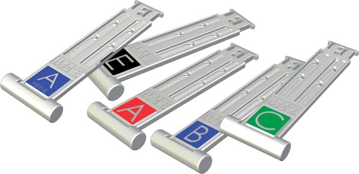
The valve interlocks as well as the keys are made of stainless steel. Individual coding guarantees the highest level of safety. It is not possible to have copies made of the keys (as can be done with simple padlock keys) due to the unique design and coding of each key.
The coded keys have been designed with ergonomics in mind and offer ease of use due to their shape, even when wearing heavy-duty safety gloves. There is no up or down position of the key. The coded keys can therefore be inserted into the lock from either direction. Inserting a key by just a few millimetres into the lock is sufficient to know that there is a correct match of key and lock. These feature guarantee a speedy work flow.
Coloured tagging make it easy to match the keys with the corresponding interlocks. Up to four lines of text are available for customer-specific engravings.
Example.. Safe isolation of a safety valve for maintenance
The type of interlock system below is designed to mechanically interlock two pressure safety valves having two upstream block valves and two downstream block valves to prevent isolation of both the relief valves at the same time and allow safe isolation of the safety valve for maintenance.
Operating condition of the valve interlock
- One PSV (PSV-A) is operational and other PSV (PSV-B) is standby
- Key B is taken from the control room
To put PSV-B into maintenance..
- Insert key B into valve #4 and close by releasing key A
- Key A can be taken to the control room to keep PSV-B isolated for maintenance
To change-over putting PSV-A into operation and PSV-B into operation..
- Insert key B into valve #1 and open by releasing key C (both safeties are online)
- Insert key C into valve #2 and close by releasing key D, which can be taken to the control room
PSV-B is now in operation and PSV-A is in standby.
To further isolate PSV-A for maintenance..
- Insert key D into valve #3 and close releasing key E
- Key E can be taken to the control room to keep PSV-A isolated for maintenance
Both PSVs will never be closed simultaneously, ensuring that at least one PSV is always available for equipment protection.
Legend..
Reference(s).. www.alcatrazinterlocks.com and www.haake-technik.com