 |
Air Cooled Heat Exchanger |
Introduction to air-cooled heat exchangers
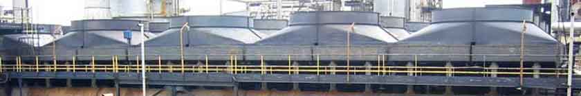
Water shortage and increasing costs, together with more recent concerns about water pollution and cooling tower plumes, have greatly reduced industry's use of water cooled heat exchangers. Consequently, when further heat integration within the plant is not possible, it is now usual to reject heat directly to the atmosphere, and a large proportion of the process cooling in refineries and chemical plants takes place in Air Cooled Heat Exchangers (AC-HEs).
There is also increasing use of Air Cooled Condensers for power stations. The basic principles are the same but these are specialized items and are normally configured as an A-frame or "roof type". These condensers may be very large-the condensers for a 4000 MW power station in South Africa have over 2300 tube bundles, 288 fans each 9.1 m in diameter and a total plot area 500 m X 70 m.
AC-HEs for process plants are normally just called Aircoolers, but should not be confused with devices for cooling air (best described as Air Chillers).
The design of an AC-HE is more complex than for a Shell and Tube Heat Exchanger, as there are many more components and variables.
The structure of an AC-HE is painted or galvanized, depending on customer specification. However, the costs are roughly the same if a multiple coat paint system is specified. Often the painted units are more expensive. There seems to be a trend toward more galvanized structures because they require virtually no maintenance. Painted structures require touch-up after installation and they often rust anyway.
Air-cooled heat exchangers are used extensively throughout the oil and gas industry, from upstream production to refineries and petrochemical plants, under high pressure and high temperature conditions, as well as corrosive fluids and environments.
How are they constructed?
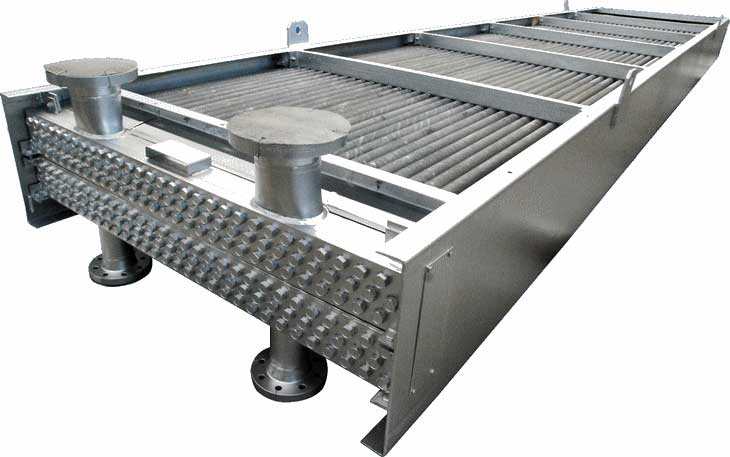
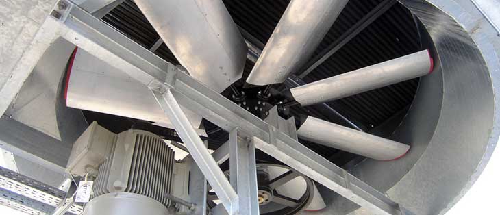
Typically, an air-cooled exchanger for process use consists of a finned-tube bundle with rectangular box headers on both ends of the tubes. Cooling air is provided by one or more fans. Usually, the air blows upwards through a horizontal tube bundle. The fans can be either forced or induced draft, depending on whether the air is pushed or pulled through the tube bundle. The space between the fan(s) and the tube bundle is enclosed by a plenum chamber which directs the air. The whole assembly is usually mounted on legs or a piperack.
The fans are usually driven be electric motors through some type of speed reducer. The speed reducers are usually either V-belts, HTD drives, or right angle gears. The fan drive assembly is supported by a steel mechanical drive support system. They usually include a vibration switch on each fan to automatically shut down a fan which has become imbalanced for some reason.
What standards air used for Air-Cooled Exchangers?
First, almost all air coolers are built to Sect. VIII of the ASME Code, since they are pressure vessels. For refinery and petrochemical services most customers include API 661 (Air-Cooled Heat Exchangers for General Refinery Service) in their specifications.
This API spec is very good since it includes all the necessary information to properly specify a cooler and provides for a high level of minimum quality in the design and fabrication of the cooler. In the back it has a very good checklist where a customer can decide exactly what type construction is needed and what options are important. These include such items as galvanizing vs. painting, types of headers, maintenance walkways and platforms, controls, and external loads on the cooler. The following details refer mostly to the API specifications.
What kinds of finned tubes are used?
The tubes can be of virtually any material available, such as carbon steel, stainless steel, Admiralty brass, or more exotic alloys. The minimum preferred outside diameter is one inch. Some manufacturers sometimes use smaller tubes, but most of the process coolers have tubes which are 1.0", 1.25", or 1.5" OD. The minimum tube wall thicknesses vary with the material. In some cases the design pressure and design temperature of the exchanger govern the minimum thickness.
The fins are almost always of aluminum material. The most common type of fin is the helically wrapped, L-footed type. These are used where the process temperatures are below about 350 °. F. The API specification calls for cast zinc bands at the ends of the tubes to prevent the fins from unwrapping. Some of the better manufacturers also use cast zinc bands at the tube supports. For higher process temperatures, most customers prefer either embedded or extruded fins. The embedded fins have the highest temperature capabilities. They are made by a process which cuts a helical groove in the OD of the tube, wraps the fin into the groove, then rolls the upset metal from the tube back against the fin to lock it into place. The tube wall must be thicker with embedded fins because of the groove.
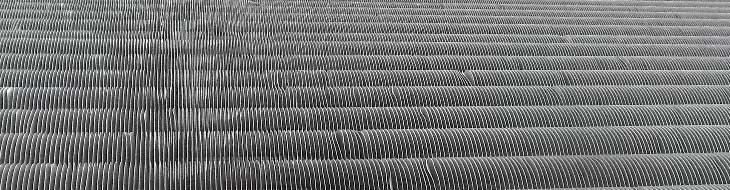
In some applications customers often prefer extruded fins. Extruded fins are made by putting an aluminum sleeve (sometimes called a muff) over the tube, then passing the tube through a machine which has rollers which squish the aluminum out to form fins. The process is similar to a thread-rolling machine. The end result is a fin which has extremely good contact with the tube, and no crevices to allow corrosion to start on the tube OD. Extruded fins are often used in coastal locations or on offshore platforms for this reason.
Some manufacturers make some rather startling claims for their "special" finned tubes. These modifications usually involve some kind of wrinkles or cuts in the fins to enhance air turbulence. We believe this is a lot of baloney. The cost of this extra turbulence is increased static pressure for the fan(s) to overcome. These claims are sometimes just too fantastic to be considered seriously.
What are headers and how are headers constructed?
Headers are the boxes at the ends of the tubes which distribute the fluid from the piping to the tubes.
Almost all headers on air-cooled exchangers are welded rectangular boxes. A vast majority of the headers are of the plug type. This means that there is a shoulder plug opposite each tube which allows access for inspection and cleaning of individual tubes. They can also be used to plug a leaking tube. The plug holes are used in the manufacturing process for access to roller expand the tubes into the headers.
The other common type of header is the cover plate or bonnet type. These are usually used in low pressure applications (say below 150 PSIG) where complete tube access is desired. This usually means applications where fouling is a potential problem and the tube bundle may require occasional internal cleaning.
As the name implies, these have a removable plate on the back side of the header opposite the tubes. The cover plate is attached to the header by a set of studs or through-bolts to a flange around the perimeter of the header. A bonnet header is similar, but opposite in construction. The whole header or bonnet bolts to the tubesheet and comes off. Bonnet headers are sometimes used where the corrosion potential of the process fluid is very high and the tubesheet material is some kind of expensive exotic alloy, such as titanium.
Headers are usually constructed of carbon steel or stainless steel, but sometimes more exotic alloys are used for corrosion resistance. The selection of materials is usually made by the customer.
Forced draft or induced draft.. Which is better?
It depends. The majority of air-cooled exchangers is of forced draft construction. Forced draft units are easier to manufacture and to maintain. The tube bundle is mounted on top of the plenum, so it can be easily removed and replaced. The fan shaft is short, since it does not have to extent from the drive unit through the tube bundle and plenum to the fan, as in an induced draft design.
Forced draft units require slightly less horsepower since the fan are moving a lower volume of air at the inlet than they would at the outlet. If the process fluid is very hot, the cooling air is hot at the outlet. This could cause problems with some fans or fan pitch actuators if the fan is exposed to very hot exhaust air. Since forced draft coolers do not have the fans exposed to hot exhaust air, they are a better choice in such cases. (API 661 par. 4.2.3.15and16 offer some guidelines for this.)
Typical induced draught air cooled heat exchanger
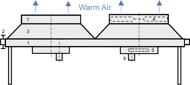
Typical forced draught air cooled heat exchanger
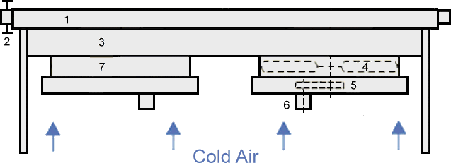
1. Tube bundle 2. Header 3. Plenum 4. Fan 5. Belt drive 6. Motor 7. Fan ring
However, induced draft units have some advantages, too. A common problem with forced draft coolers is accidental warm air recirculation. This happens when the hot exhaust air is pulled back in to the fans. Since a forced draft cooler has a low air velocity at the exhaust from the bundle and a high velocity through the fan, a low pressure area is created around the fan, causing the hot air to be pulled over the side or end of the bay.
For this same reason, there should never be a small space between the bays of a bank of forced-draft cooler. Induced draft cooler have a high exhaust air velocity through the top-mounted fan, and a lower velocity into the face of the tube bundle below. This tends to minimize the probability of accidental air recirculation. Also an induced draft plenum does not have to support the tube bundle so some weight can often be saved in this area.
Plenums, dispersion angle, and fan coverage
The API specification includes a number of paragraphs about fan coverage and dispersion angle. This is for a very good reason. The actual air coming from a fan does not distribute itself evenly at first. The most air flow is seen around the fan tip area. If you measure the air flow across the face of a tube bundle, it is often very different around the fan blade tip as opposed to the center of the fan or the corner of the bundle. However, as the plenum becomes deeper, this localized effect is diminished as the air becomes more evenly distributed. All of the heat transfer programs assume that the air is distributed perfectly evenly.
The fan coverage is the ratio of the fan area to the bundle face area. The higher this ratio, the better the fan coverage. The API minimum is 40% with a 45 degree maximum dispersion angle from the fan ring to the middle of the tube bundle at the middle of the sides or the middle of the ends of each fan chamber. More fan coverage or a lower dispersion angle can improve the air distribution. (See Figure 6 on Page 14 of API 661for a sketch of this.)
A few manufacturers actually improve on this idea one step more, by using rounded and eased fan rings. Rounded and eased rings offer two advantages compared to the conventional fan rings. First, they enhance the distribution of the air. Secondly, they reduce the air pressure drop through the fan ring, slightly reducing the fan brake horsepower. When designing their coolers, some cooler manufacturers base their fan designs on the use of rounded and eased rings, even though they don't build them this way.
References
- API Standard 661 Air-Cooled Heat Exchangers for General Refinery Service, 3rd ed., Washington D.C.. American Petroleum Institute.
- Air-Cooled Heat Exchangers, Jim Stone, Stone Process Equipment Co.
- Briggs.D. E. and Young, E. H. Convection heat transfer and pressure drop of air flowing across triangular pitch banks of finned tubes, Chem. Engng. Progr., Symp. Ser., 59 (41).. 1-10.
- ESDU High-fin staggered tube banks.. Heat transfer and pressure drop for turbulent single phase gas flow, Item No. 86022, London.. Engineering Sciences Data Unit.
- ESDU Selection and costing of heat exchangers, Item No. 92013, London.. Engineering Sciences Data Unit.
- PFR Engineering Systems Inc. Heat transfer and pressure drop characteristics of dry tower extended surfaces, Part II.. Data analysis and correlation, Report BNWL-PFR-7-102, Marina del Rey, California.
- Robinson, K. K. and Briggs, D. E. Pressure drop of air flowing across triangular pitch banks of finned tubes, Chem. Engng. Progr., Symp. Ser., 62 (64).. 177-184.
Related Post(s)
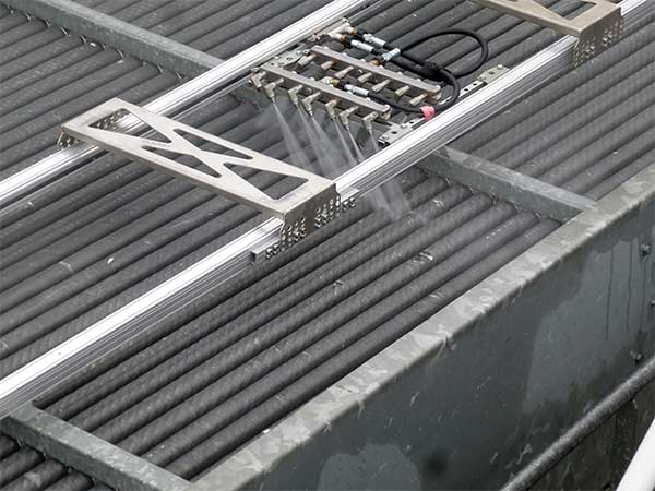
Keeping ACHE or ACC air-cooled heat exchangers and specific parts clean, is very important to maintain quality and extend life...