Ultrasonic Testing (UT) |
Ultrasonic nondestructive testing, also known as ultrasonic NDT or simply UT, is a method of characterizing the thickness or internal structure of a test piece through the use of high frequency sound waves. The frequencies, or pitch, used for ultrasonic testing are many times higher than the limit of human hearing, most commonly in the range from 500 KHz to 20 MHz.
What sort of materials can be tested..
In industrial applications, ultrasonic testing is widely used on metals, plastics, composites, and ceramics. The only common engineering materials that are not suitable for ultrasonic testing with conventional equipment are wood and paper products. Ultrasonic technology is also widely used in the biomedical field for diagnostic imaging and medical research.
Principle of ultrasonic testing.
LEFT..A probe sends a sound wave into a test material. There are two indications, one from the
initial pulse of the probe, and the second due to the back wall echo.
RIGHT..A defect creates a third indication and simultaneously reduces the amplitude of the back
wall indication.
How does it work..
High frequency sound waves are very directional, and they will travel through a medium (like a piece of steel or plastic) until they encounter a boundary with another medium (like air), at which point they reflect back to their Reference(s). By analyzing these reflections it is possible to measure the thickness of a test piece, or find evidence of cracks or other hidden internal flaws.
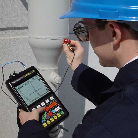
In ultrasonic testing, an ultrasound transducer connected to a diagnostic machine is passed over the object being inspected. The transducer is typically separated from the test object by a couplant (such as oil) or by water, as in immersion testing.
There are two methods of receiving the ultrasound waveform, reflection and attenuation.
In reflection (or pulse-echo) mode, the transducer performs both the sending and the receiving of the pulsed waves as the "sound" is reflected back to the device. Reflected ultrasound comes from an interface, such as the back wall of the object or from an imperfection within the object. The diagnostic machine displays these results in the form of a signal with an amplitude representing the intensity of the reflection and the distance, representing the arrival time of the reflection.
In attenuation (or through-transmission) mode, a transmitter sends ultrasound through one surface, and a separate receiver detects the amount that has reached it on another surface after traveling through the medium. Imperfections or other conditions in the space between the transmitter and receiver reduce the amount of sound transmitted, thus revealing their presence. Using the couplant increases the efficiency of the process by reducing the losses in the ultrasonic wave energy due to separation between the surfaces.
What are the advantages of ultrasonic testing..
Ultrasonic testing is completely nondestructive. The test piece does not have to be cut, sectioned, or exposed to damaging chemicals. Access to only one side is required, unlike measurement with mechanical thickness tools like calipers and micrometers. There are no potential health hazards associated with ultrasonic testing, unlike radiography. When a test has been properly set up, results are highly repeatable and reliable.
What are the potential limitations of ultrasonic testing..
Ultrasonic flaw detection requires a trained operator who can set up a test with the aid of appropriate reference standards and properly interpret the results. Inspection of some complex geometries may be challenging. Ultrasonic thickness gages must be calibrated with respect to the material being measured, and applications requiring a wide range of thickness measurement or measurement of acoustically diverse materials may require multiple setups. Ultrasonic thickness gages are more expensive than mechanical measurement devices.
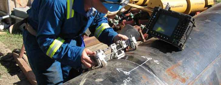
Ultrasonic Testing of Welds
One of the most useful characteristics of ultrasonic testing is its ability to determine the exact position of a discontinuity in a weld. This testing method requires a high level of operator training and competence and is dependant on the establishment and application of suitable testing procedures. This testing method can be used on ferrous and nonferrous materials, is often suited for testing thicker sections accessible from one side only, and can often detect finer lines or plainer defects which may not be as readily detected by radiographic testing.
Standards
International Organization for Standardization (ISO)
- ISO 7963, Non-destructive testing - Ultrasonic testing - Specification for calibration block No. 2
- ISO/DIS 11666, Non-destructive testing of welds - Ultrasonic testing of welded joints - Acceptance levels
- ISO/DIS 17640, Non-destructive testing of welds - Ultrasonic testing of welded joints
- ISO 22825, Non-destructive testing of welds - Ultrasonic testing - Testing of welds in austenitic steels and nickel-based alloys
European Committee for Standardization (CEN)
- EN 583, Non-destructive testing - Ultrasonic examination
- EN 1330-4, Non destructive testing - Terminology - Part 4.. Terms used in ultrasonic testing
- EN 1712, Non-destructive testing of welds - Ultrasonic testing of welded joints - Acceptance levels
- EN 1713, Non-destructive testing of welds - Ultrasonic testing - Characterization of indications in welds
- EN 1714, Non-destructive testing of welds - Ultrasonic testing of welded joints
- EN 12223, Non-destructive testing - Ultrasonic examination - Specification for calibration block No. 1
- EN 12668-1, Non-destructive testing - Characterization and verification of ultrasonic examination equipment - Part 1.. Instruments
- EN 12668-2, Non-destructive testing - Characterization and verification of ultrasonic examination equipment - Part 2.. Probes
- EN 12668-3, Non-destructive testing - Characterization and verification of ultrasonic examination equipment - Part 3.. Combined equipment
- EN 12680, Founding - Ultrasonic examination
- EN 14127, Non-destructive testing - Ultrasonic thickness measurement
Ultrasonic Testing FAQ
- What is an ultrasonic transducer..
A transducer is any device that converts one form of energy into another. An ultrasonic transducer converts electrical energy into mechanical vibrations (sound waves), and sound waves into electrical energy. Typically, they are small, hand-held assemblies that come in a wide variety of frequencies and style to accommodate specific test needs.
- What is an ultrasonic thickness gage..
An ultrasonic thickness gage is an instrument that generates sound pulses in a test piece and very precisely measures the time interval until echoes are received. Having been programmed with the speed of sound in the test material, the gage utilizes that sound velocity information and the measured time interval to calculate thickness via the simple relationship [distance] equals [velocity] multiplied by [time].
- How accurate is ultrasonic thickness gaging..
Under optimum conditions, commercial ultrasonic gages can achieve accuracies as high as +/- 0.001 mm, with accuracies of +/- 0.025 mm or better possible in most common engineering materials. Factors affecting accuracy include the uniformity of sound velocity the test material, the degree of sound scattering or absorption, the surface condition, and the accuracy and care with which the instrument has been calibrated for the application at hand.
- Who uses ultrasonic gages..
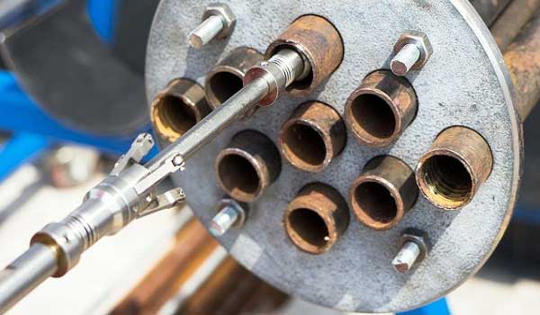
A major use for ultrasonic gages is the measurement of remaining wall thickness in corroded pipes and tanks. The measurement can be made quickly and easily without needing access to the inside or requiring the pipe or tank to be emptied. Other important applications include measuring the thickness of molded plastic bottles and similar containers, turbine blades and other precision machined or cast parts, small diameter medical tubing, rubber tires and conveyor belts, fiberglass boat hulls, and even contact lenses.
- What is an ultrasonic flaw detector..
Sound waves traveling through a material will reflect in predictable ways off of flaws such as cracks and voids. An ultrasonic flaw detector is an instrument that generates and processes ultrasonic signals to create a waveform display that can be used by a trained operator to identify hidden flaws in a test piece. The operator identifies the characteristic reflection pattern from a good part, and then looks for changes in that reflection pattern that may indicate flaws.
- What kind of flaws can you find with one..
A wide variety of cracks, voids, disbonds, inclusions, and similar problems that affect structural integrity can all be located and measured with ultrasonic flaw detectors. The minimum detectable flaw size in a given application will depend on the type of material being tested and the type of flaw under consideration.
- Who uses ultrasonic flaw detectors..
Ultrasonic flaw detectors are widely used in critical safety-related and quality-related applications involving structural welds, steel beams, forgings, pipelines and tanks, aircraft engines and frames, automobile frames, railroad rails, power turbines and other heavy machinery, ship hulls, castings, and many other important applications.
- What other types of instruments are available..
Ultrasonic imaging systems are used to generate highly detailed pictures similar to x-rays, mapping the internal structure of a part with sound waves. Phased array technology originally developed for medical diagnostic imaging is used in industrial situations to create cross-sectional pictures. Large scanning systems are used by the aerospace industry and metalworking suppliers to check for hidden flaws in both raw materials and finished parts. Ultrasonic pulser/receivers and signal analyzers are used in a variety of materials research applications.
Reference..www.olympus-ims.com
Related Post(s)
IRIS is a technique that can be applied on both ferrous and non- ferrous materials and even on non-conductive materials...
Positive Material Identification is one of the more specialised non destructive testing methods by which the alloy composition of materials...