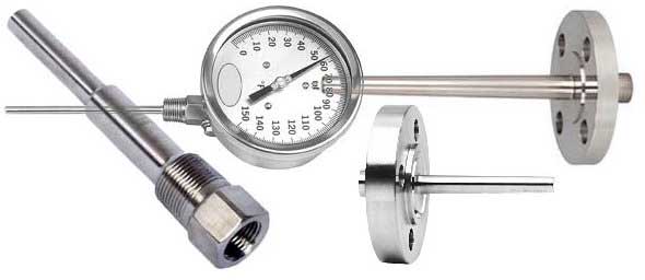
Temperature Measurement by Thermowell
A thermowell is a pressure tight receptacle designed to accept a temperature sensing element and provide a means to insert that element into a vessel or pipe.
The American Society for Testing and Materials (ASTM) has defined the term thermowell as a closed-end reentrant tube designed for insertion of a temperature-sensing element, and provided with means for a pressure-tight attachment to a vessel.
Principles of Operation
A thermowell acts as a barrier between a process medium and the sensing element of a temperature measuring device. It protects against corrosive process media, as well as media contained under pressure or flowing at a high velocity. A thermowell also allows the sensing element to be removed from the application while maintaining a closed system.
Why use a Thermowell..
If the measurement is not critical either to the safety of the plant or to the efficiency of the production, and if the process fluid is not particularly aggressive or dangerous, it may be possible to insert a stainless steel, sheathed, industrial thermometer into the plant pipeline through a suitable compression fitting. Obviously, the thermometer could not be removed while the plant is running and should a problem occur with the measurement, maintenance will be delayed until the process can be stopped and the line drained and made safe.
What kinds of Thermowells exist..
Thermowells are available for use with all Temperature Instrumentation and Control Products, including.. Thermometers, Thermocouples, RTDs, Temperature Recorders, and Temperature Controllers.
Connections.. Thermowells are available in a variety of process connection styles. Threaded connections in 1/2, 3/4 and 1 NPT are the most widely specified. Socket weld, weld-in, raised face flanged connection styles are also available. Bimetal Thermowells are provided with a 1/2 NPSM instrument connection to allow for pressure relief within the thermowell.
U-Length.. The U-length (insertion length) of a thermowell indicates its insertion depth into a process vessel or piping system and is measured from the tip of the thermowell to the underside of the threads. The U-length must equal or exceed the length of the sensitive portion of the temperature instrument's stem or bulb.
Shank.. Thermowells are available in stepped, tapered, and straight shank configurations. Stepped shank thermowells are normally used on standard duty applications. Tapered shank thermowells are designed for use on heavy duty applications. Straight shank thermowells are designed for use with instruments that have wide stem diameters or short stem lengths.
Lagging Extension.. Lagging extension thermowells are used on applications where insulation covers the vessel or piping system. The extension length (T-length) is the measurement between the instrument connection and process connection of the thermowell.
What kinds of materials can be used to make Thermowells..
The thermowell protects the instrument from the pressure, flow-induced forces, and chemical effects of the process fluid. Typically a thermowell is made from metal bar stock, bored to accept the temperature sensor, and with a screw or flange for mounting. The inner end of the thermowell may be of reduced diameter to improve the speed of response. For low pressures and temperatures, Teflon may be used to make a thermowell. Thermowells in a variety of materials, including.. brass, carbon steel,stainless steel, Monel, Carpenter 20, Hastelloy, Inconel, Incoloy, Nickel and Titanium.
Where temperatures are high and the pressure differential is small, a protection tube may be used with a bare thermocouple element. These are made of alumina to prevent chemical attack of the platinum or other thermocouple elements, and may be in turn be inserted into a heavy silicon-carbide outer protection tube if increased protection is required.
Since the mass of the thermowell must be heated to the process temperature, and since the walls of the thermowell conduct heat out of the process, accuracy and speed of response of the sensor is affected.
Thermowell in a Tee Configuration
Additional considerations for Thermowell design
Thermowells are typically installed in piping systems and subject to both hydrostatic and aerodynamic forces. Vortex shedding is the dominant concern for thermowells in cross-flow applications and is capable of forcing the thermowell into resonance with the possibility of fatigue failure not only of the thermowell but also of the temperature sensor. The conditions for flow-induced resonance generally govern the design of the thermowell apart from its pressure rating and materials of construction.
Flow-induced motion of the thermowell occurs both in-line with and transverse to the direction of flow with the fluid forces acting to bend the thermowell. In most applications the transverse component of the fluid forces resulting from vortex shedding tends to govern the onset of flow-induced resonance, with a forcing frequency equal to the vortex shedding rate. In liquids and in high pressure compressible fluids, a smaller but nonetheless significant component of motion in the flow-direction is also present and occurs at nearly twice the vortex shedding rate.
ASME PTC 19.3 TW - 2010
This code is an expanded version of the thermowell section contained in the PTC 19.3-1974, and incorporates the latest theory in the areas of natural frequency, Strouhal frequency, in-line resonance and stress evaluation.
ASME responded to changing industry demands for a more comprehensive set of thermowell evaluations. Key enhancements over the 1974 edition include..
- Expanded coverage for thermowell geometry
- Natural frequency correction factors for mounting compliance, added fluid mass, and sensor mass
- Consideration for partial shielding from flow
- Intrinsic thermowell damping
- Steady state and dynamic stress evaluations
- Improved allowable fatigue limit definition
PTC 19.3 has been the standard used by piping designers since it's release and has been highly successful in the industry. The new, expanded PTC 19.3 TW edition developed by end users and manufacturers builds on decades of industry and research data to make it the new worldwide authority for thermowell design safety.
Intended for piping designers, instrument engineers, instrument designers and plant I/C engineers/designers, plant engineers, plant safety engineers, process engineers, thermowell manufacturers, instrument manufacturers, anyone who assembles thermowell bids or design specifications, and regulatory agencies.
Related Post(s)
A pressure switch is a mechanical or electronic device that is activated when the pressure of the process fluid reaches a certain threshold or set point...