 |
Dynamic Spring Supports |
There are different types of dynamic or flexible support. Each has its own purpose. Dynamic supports support the pipe in vibrations, seismic, winds and even take loads in working conditions.
To prevent constraints in the system, thermal expansion in the piping and the other piping components must not be hindered. The piping must therefore be supported in a correspondingly elastic manner so to compensate slight vertical displacements in the piping, Spring components are used as supports.
Variable Spring Supports
Pipework and/or vessels subject to temperature change or subsidence, etc. which give rise to vertical displacements should be supported by a resilient device which will absorb/accommodate the movement. For relatively small displacements (up to about 75mm) the variable spring support is recommended.
Standard ranges of variable spring supports are produced in four basic travel ranges; 35mm, 70mm, 140mm and 210mm. The travels stated are the maximum working range of the springs. This full travel can be used providing the necessary calculations are carried out to ensure that the connecting equipment and pipework can withstand the large load changes that occur during pipe movement.
Most national standards do limit the load variation to maximum of 25%. It is therefore usual to select variable spring supports on this basis.
In keeping with generally accepted practice, it's recommend that the actual pipe load is correctly supported when the pipe is in its normal working position. This ensures no abnormal or excessive forces, due to out of balance supporting effort, is transferred to the pipework in its stressed working condition.
Whether this or any other principle is followed for the selection of variable spring supports, care must be taken to ensure that sufficient travel is available in the spring assembly to permit free movement of the pipe within the required pipework movement range cold or hot.
Some types of Variable Spring Hangers and Supports
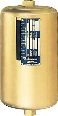
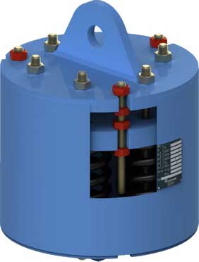
This type of Spring Hanger, the one most frequently used, is fitted with an upper connection for suspension. It is installed wherever the surrounding location offers a suitable connection point and sufficient space. The upper connections can be universally adapted with standard components to any given situation.
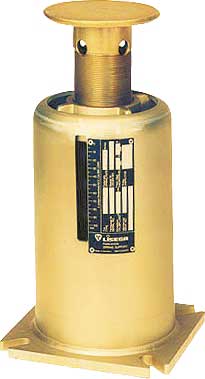
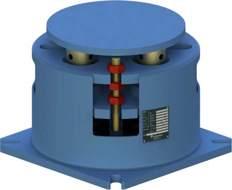
If the installation location does not permit suspension, then this Spring Support is a suitable alternative as a "prop" support.
Where there is considerable horizontal displacement of the support load, and steel slides on steel, lateral forces can under certain conditions have an adverse effect on the operation of the support system.
To take precautions against this, the use of PTFE bearings is recommended. In this case the counter bearing should have a stainless steel surface.
Load setting and blocking
Spring hangers and supports are preset at the works to the installation load and blocked in both directions of movement. Blocking is necessary to take up additional loads during pickling, flushing, or hydrostatic tests. The factory settings are carried out on electronically controlled test benches..
- with spring hangers, values set at the factory are stamped onto a riveted name plate
- the installation position is marked on the travel scale
- cold and hot settings are marked on the travel scale with a white and red sticker respectively
- the blocking device can be blocked in any position
- The blocking pieces can be reinserted in any required position
Spring hangers and supports should be set in such a way that the spring load and the piping weight correspond with the cold load position. The corresponding hot load position results from the theoretically determined pipe movement (travel) and the spring rate. The load difference between the cold and hot positions acts on the piping as a reaction force and is limited by the relevant design specifications.Generally, the max. permissible load deviation amounts to 25% of the operating load.
Installation Instructions
Hanging type supports are installed in position on the supporting steelwork, the sling rod is connected between the pipe attachment (clamp or lug) and the spring hanger turnbuckle. Rotation of the turnbuckle, transfers the pipe load to the spring hanger.
Base mounted supports are located in the desired position beneath the pipe - load is transferred from the pipe to the support by means of rotating the central column.
 |
At no point prior to or during the installation process should the travel stops be removed. attempting to remove the travel stops without all load removed from the stops can result in property damage or personal injury. |
Preset Lock Removal
This range of variable spring supports is preset to the installed load position prior to despatch. The preset locks are fitted with a label drawing attention to the fact that these must be removed prior to system operation. When fitted, the hydrostatic locks prevent the spring deflecting during hydrostatic tests. They also must be removed prior to system operation. The preset locks fitted to hanging types are removed by rotating the turnbuckle to increase load until the locks are free - the locks are then withdrawn from the spring unit. In the case of the base mounted type, simply rotate the centre column to increase load until the locks are free - the locks are then withdrawn from the spring unit. For the removal of hydrostatic test locks the procedure is repeated, except the turnbuckle/load column is rotated to reduce load. All locks are removed by cutting the temporary banding holding them in position in the unit. The locks can then be withdrawn.
 |
Travel stops must be removed before any testing or cleaning of the system above ambient temperatures is done. should this cause greater loading than the design loads, temporary supports must be provided. |
Adjustment
When installed the spring units should be adjusted until the load indicators point to the installed load position. The units should be checked following a reasonable period of operation (preferably in the operating condition). The load indicator should be indicating the operating load. If minor differences are apparent then the units should be adjusted to the operating position; no further adjustments should be necessary. If major differences are noted then either consult the designer department for advice, prior to making adjustments.
 |
Attempting to remove travel stops without all loading removed from the stops may result in property damage or personal injury. |
Maintenance
- Each Spring Support must be inspected annually to verify the correct setting of the load indicator.
If required, the support should be adjusted. - All dust, soot, and foreign objects which may impair hanger operation shall be removed. No further maintenance is required.
 |
Under no circumstances should a spring support be disassembled. the compression spring is pre-compressed and can cause severe injury. |
Reference(s) .. Lisega, Carpenter and Paterson Ltd., Anvil