 |
Double Block and Bleed |
The primary function of a double block and bleed system is for isolation and the secondary function is for intervention.
Under certain conditions double block and bleed systems are needed to prevent product contamination or where it is necessary to remove essential equipment from service for cleaning or repairs while the unit continues in operation.
Of course, such equipment must be provided with a spare or it must be possible to bypass it temporarily without shutting down the unit.
The nature of the fluid, its pressure and temperature, and many other factors must be considered when determining the need for double block and bleed systems.
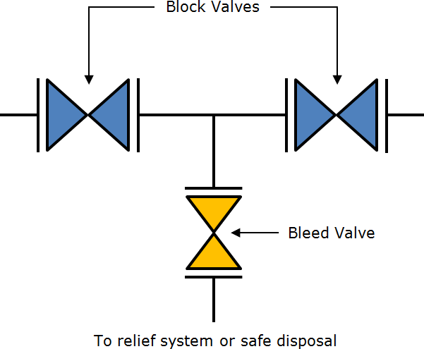
Generally, block Valves should be considered for the onstream isolation of equipment if the fluid is flammable or otherwise hazardous, or if the fluid is in high-pressure or high-temperature service. Where double block Valves are used, a NPS 3/4 or larger bleed Valve should be installed between the block Valves.
The purpose of the bleed Valve is twofold. First, the bleed ensures that the upstream Valve is in fact tight before slipping in a blind off the downstream block Valve. The bleed connection also permits the safe withdrawal of moderate leakage from the upstream Valve to again assure the tight shutoff of the downstream Valve.
Depending on the service conditions, it may be possible to use a single block Valve with a body bleed to provide double block and bleed provisions for onstream isolation of equipment.
Gate Valves with flexible wedges and with body or Bonnet bleed Valve can serve this purpose if specifically tested in accordance with API-598 for double block and bleed quality Valves.
Some Ball Valves and nonlubricated Plug Valves, when equipped with a Valve body bleed between the seats, can also be satisfactory substitutes for double block Valves.
Testing for double block and bleed quality Valves requires the pressure-testing of each seat, with leakage measured through the Valve body bleed as a means of substantiating the independent leak tightness of both the upstream and downstream seats of the Valve.
Double Block and Bleed Animation
Double Block and Bleed Valves
The Double Block and Bleed Valve or a DBBV can perform the tasks of 3 separate Valves (2 separate isolations and 1 drain Valve) which apart from being hugely space saving can also save on weight and time due to installation and maintenance practices requiring much less work and the operator being able to locate and operate all 3 Valves in one location.
Double block and bleed Valves operate on the principle that isolation can be achieved from both the upstream and downstream process flow / pressures.
This is achieved by two ball, gate, globe, needle, etc. Valves placed back to back, with a third "isolatable" Valve in the centre cavity.
Once isolation has been achieved in one or more of the main process isolation Valves, the cavity that is created between these isolations can be drained. This is useful for flow diverting, sampling or injection situations, and for maintenance and or integrity check situations where seat leakage can be monitored through the third "bleed" Valve.
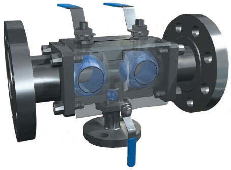
The image above gives you a good impression, how a DBB Valve is constructed. In this image example, three balls are mounted. 2 large balls that serve as a block (both are closed), and the small ball serve as the bleed (ball is in open position).
Image comes from www.habonim.com. It is a DBB Valve in the dual-Safe series. For more information about Habonim click the PDF icon below.
Isolation (Stop) Valves in Pressure-Relief Piping
The article below (text) comes from the American Petroleum Institute (API)
Sizing, Selection, and Installation of Pressure-Relieving Devices in Refineries, Part II-Installation
API recommended practice 520 fifth edition
Isolation (Stop) Valves in Pressure-Relief Piping
Isolation block Valves may be used for maintenance purposes to isolate a pressure-relief device from the equipment it protects or from its downstream disposal system. Since improper use of an isolation Valve may render a pressure-relief device inoperative, the design, installation, and administrative controls placed on these isolation block Valves should be carefully evaluated to ensure that plant safety is not compromised. A pressure-relief device shall not be used as a block Valve to provide positive isolation.
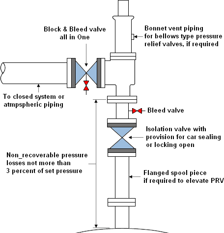
Inlet Isolation Valves
a. Valves shall be full bore. ASME Section VIII Appendix M recommends the use of full area isolation (stop) Valves. Mandatory paragraph UG-135 (b)(1), of ASME Section VIII, requires that the opening through all pipe and fittings between a pressure vessel and its pressure-Relief Valve shall have the area of the pressure-relief device inlet. It is therefore recommended that the minimum flow area in the isolation Valve be equal to or greater than the inlet area of the pressure-Relief Valve. The minimum flow area of the isolation Valve and the inlet area of the pressureRelief Valve can be obtained from the isolation Valve manufacturer and the pressure-Relief Valve manufacturer.
b. Valves shall be suitable for the line service classification.
c. Valves shall have the capability of being locked or carsealed open.
d. When Gate Valves are used, they should be installed with stems oriented horizontally or, if this is not feasible, the stem could be oriented downward to a maximum of 45° from the horizontal to keep the gate from falling off and blocking the flow.
e. A bleed Valve should be installed between the isolation Valve and the pressure-relief device to enable the system to be safely depressurized prior to performing maintenance. This bleed Valve can also be used to prevent pressure build-up between the pressure-relief device and the closed outlet isolation Valve.
f. Consideration should be given to using an interlocking system between the inlet and outlet isolation Valves to assist with proper sequencing.
g. Consideration should be given to painting the isolation Valve a special color or providing other identification. When placing the pressure-relief device into service, it is recommended to gradually open the isolation Valve. This ramping up of system pressure can help prevent unwanted opening of a Valve seat due to the momentum of the fluid. The inlet Valve must be open fully.
Outlet Isolation Valves
a. Valves shall be full bore. ASME Section VIII Appendix M recommends the use of full area isolation (stop) Valves. To help minimize the built-up back pressure, it is recommended that the minimum flow area in the outlet isolation Valve be equal to or greater than the outlet area of the pressure-Relief Valve. The minimum flow area of the outlet isolation Valve and the outlet area of the pressure-Relief Valve can be obtained from the isolation Valve manufacturer and the pressure-Relief Valve manufacturer respectively.
b. Valves shall be suitable for line service classification.
c. Valves shall have the capability of being locked or carsealed open. This outlet isolation shall never be closed while the vessel is in operation without using an inlet isolation Valve that has first been closed with the space between the inlet isolation Valve and the pressure-Relief Valve adequately depressured.
d. A bleed Valve should be installed between the outlet isolation Valve and pressure-relief device to enable the system to be safely depressurized prior to performing maintenance. This bleed Valve can also be used to prevent pressure build-up between the pressure-relief device and the closed outlet isolation Valve.
e. Consideration should be given to using an interlocking system between the inlet and outlet isolation Valves to assist with proper sequencing.
f. Consideration should be given to painting the isolation Valve a special color or providing other identification. When the outlet isolation Valve is used in conjunction with an inlet isolation Valve, upon commissioning the pressurerelief device, the outlet isolation Valve shall be opened fully prior to the inlet isolation Valves.
True meaning of Double Block and Bleed
Rudy Garza, Mechanical Lead-Static Equipment Engineering Group at ExxonMobil Development Company, gave a presentation at the VMA Technical Seminar in San Antonio entitled "Isolation Philosophies" in which he asserted that many people take the term "Double Block and Bleed" (DBB) to mean the same thing as Double Positive Isolation" (DPI).
It's time to do maintenance on a section of process. You don't want to shut down the entire facility, so you decide to block off and depressurize just the section you're working on. Just upstream is a double block and bleed Valve - a trunnion-mounted Ball Valve with self-relieving seals and a bleed Valve to vent the cavity. You close the Ball Valve and open the bleeder. Now you can de-pressurize the line downstream and open it up to work on it.
No so fast, says Rudy Garza. You may think that Valve gives you double isolation, but it doesn't and that could be dangerous... More..