 |
Pressure Relief valves |
A pressure Relief Valve is a safety device designed to protect a pressurized vessel or system during an overpressure event.
An overpressure event refers to any condition which would cause pressure in a vessel or system to increase beyond the specified design pressure or maximum allowable working pressure (MAWP).
The primary purpose of a pressure Relief Valve is protection of life and property by venting fluid from an overpressurized vessel.
Many electronic, pneumatic and hydraulic systems exist today to control fluid system variables, such as pressure, temperature and flow. Each of these systems requires a power source of some type, such as electricity or compressed air in order to operate. A pressure Relief Valve must be capable of operating at all times, especially during a period of power failure when system controls are nonfunctional. The sole source of power for the pressure Relief Valve, therefore, is the process fluid.
Once a condition occurs that causes the pressure in a system or vessel to increase to a dangerous level, the pressure Relief Valve may be the only device remaining to prevent a catastrophic failure. Since reliability is directly related to the complexity of the device, it is important that the design of the pressure Relief Valve be as simple as possible.
The pressure Relief Valve must open at a predetermined set pressure, flow a rated capacity at a specified overpressure, and close when the system pressure has returned to a safe level. Pressure Relief Valves must be designed with materials compatible with many process fluids from simple air and water to the most corrosive media. They must also be designed to operate in a consistently smooth and stable manner on a variety of fluids and fluid phases.
Spring Loaded Pressure Relief Valve
The basic spring loaded pressure Relief Valve has been developed to meet the need for a simple, reliable, system actuated device to provide overpressure protection.
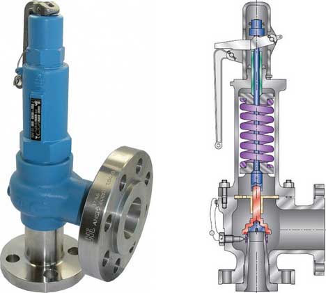
The image on the right shows the construction of a spring loaded pressure Relief Valve.
The Valve consists of a Valve inlet or nozzle mounted on the pressurized system, a disc held against the nozzle to prevent flow under normal system operating conditions, a spring to hold the disc closed, and a body/Bonnet to contain the operating elements. The spring load is adjustable to vary the pressure at which the Valve will open.
When a pressure Relief Valve begins to lift, the spring force increases. Thus system pressure must increase if lift is to continue. For this reason pressure Relief Valves are allowed an overpressure allowance to reach full lift. This allowable overpressure is generally 10% for Valves on unfired systems. This margin is relatively small and some means must be provided to assist in the lift effort.
Most pressure Relief Valves, therefore, have a secondary control chamber or huddling chamber to enhance lift. As the disc begins to lift, fluid enters the control chamber exposing a larger area of the disc to system pressure.
This causes an incremental change in force which overcompensates for the increase in spring force and causes the Valve to open at a rapid rate. At the same time, the direction of the fluid flow is reversed and the momentum effect resulting from the change in flow direction further enhances lift. These effects combine to allow the Valve to achieve maximum lift and maximum flow within the allowable overpressure limits. Because of the larger disc area exposed to system pressure after the Valve achieves lift, the Valve will not close until system pressure has been reduced to some level below the set pressure. The design of the control chamber determines where the closing point will occur.
The difference between the set pressure and the closing point pressure is called blowdown and is usually expressed as a percentage of set pressure.
Balanced Bellows Valves and Balanced Piston Valves
When superimposed back pressure is variable, a balanced bellows or balanced piston design is recommended. A typical balanced bellow is shown on the right. The bellows or piston is designed with an effective pressure area equal to the seat area of the disc. The Bonnet is vented to ensure that the pressure area of the bellows or piston will always be exposed to atmospheric pressure and to provide a telltale sign should the bellows or piston begin to leak. Variations in back pressure, therefore, will have no effect on set pressure. Back pressure may, however, affect flow.
Pressure Relief Valve Bellow Type
Other designs of Relief Valves
Safety Valve
A safety Valve is a pressure Relief Valve actuated by inlet static pressure and characterized by rapid opening or pop action. (It is normally used for steam and air services.)
- Low-Lift Safety Valve
A low-lift safety Valve is a safety Valve in which the disc lifts automatically such that the actual discharge area is determined by the position of the disc. - Full-Lift Safety Valve
A full-lift safety Valve is a safety Valve in which the disc lifts automatically such that the actual discharge area is not determined by the position of the disc.
Relief Valve
A Relief Valve is a pressure relief device actuated by inlet static pressure having a gradual lift generally proportional to the increase in pressure over opening pressure. It may be provided with an enclosed spring housing suitable for closed discharge system application and is primarily used for liquid service.
Safety Relief Valve
A safety Relief Valve is a pressure Relief Valve characterized by rapid opening or pop action, or by opening in proportion to the increase in pressure over the opening pressure, depending on the application and may be used either for liquid or compressible fluid.
- Conventional Safety Relief Valve
A conventional safety Relief Valve is a pressure Relief Valve which has its spring housing vented to the discharge side of the Valve. The operational characteristics (opening pressure, closing pressure, and relieving capacity) are directly affected by changes of the back pressure on the Valve. - Balanced Safety Relief Valve
A balanced safety Relief Valve is a pressure Relief Valve which incorporates means of minimizing the effect of back pressure on the operational characteristics (opening pressure, closing pressure, and relieving capacity).
Pilot-Operated Pressure Relief Valve
A pilotoperated pressure Relief Valve is a pressure Relief Valve in which the major relieving device is combined with and is controlled by a self-actuated auxiliary pressure Relief Valve.
Power-Actuated Pressure Relief Valve
A poweractuated pressure Relief Valve is a pressure Relief Valve in which the major relieving device is combined with and controlled by a device requiring an external source of energy.
Temperature-Actuated Pressure Relief Valve
A temperature-actuated pressure Relief Valve is a pressure Relief Valve which may be actuated by external or internal temperature or by pressure on the inlet side.
Vacuum Relief Valve
A vacuum Relief Valve is a pressure relief device designed to admit fluid to prevent an excessive internal vacuum; it is designed to reclose and prevent further flow of fluid after normal conditions have been restored.
Codes, Standards and recommended Practices
Many Codes and Standards are published throughout the world which address the design and application of pressure Relief Valves. The most widely used and recognized of these is the ASME Boiler and Pressure Vessel Code, commonly called the ASME Code.
Most Codes and Standards are voluntary, which means that they are available for use by manufacturers and users and may be written into purchasing and construction specifications. The ASME Code is unique in the United States and Canada, having been adopted by the majority of state and provincial legislatures and mandated by law.
The ASME Code provides rules for the design and construction of pressure vessels. Various sections of the Code cover fired vessels, nuclear vessels, unfired vessels and additional subjects, such as welding and nondestructive examination. Vessels manufactured in accordance with the ASME Code are required to have overpressure protection. The type and design of allowable overpressure protection devices is spelled out in detail in the Code.
Terminology
The following definitions are taken from DIN 3320 but it should be noted that many of the terms and associated definitions used are universal and appear in many other standards. Where commonly used terms are not defined in DIN 3320 then ASME PTC25.3 has been used as the source of reference. This list is not exhaustive and is intended as a guide only; it should not be used in place of the relevant current issue standard..
- Operating pressure (working pressure)
is the gauge pressure existing at normal operating conditions within the system to be protected. - Set pressure
is the gauge pressure at which under operating conditions direct loaded safety Valves commence to lift. - Test pressure
is the gauge pressure at which under test stand conditions (atmospheric backpressure) direct loaded safety Valves commence to lift. - Opening pressure
is the gauge pressure at which the lift is sufficient to discharge the predetermined flowing capacity. It is equal to the set pressure plus opening pressure difference. - Reseating pressure
is the gauge pressure at which the direct loaded safety Valve is re-closed. - Built-up backpressure
is the gauge pressure built up at the outlet side by blowing. - Superimposed backpressure
is the gauge pressure on the outlet side of the closed Valve. - Backpressure
is the gauge pressure built up on the outlet side during blowing (built-up backpressure + superimposed backpressure). - Accumulation
is the increase in pressure over the maximum allowable working gauge pressure of the system to be protected. - Opening pressure difference
is the pressure rise over the set pressure necessary for a lift suitable to permit the predetermined flowing capacity. - Reseating pressure difference
is the difference between set pressure and reseating pressure. - Functional pressure difference
is the sum of opening pressure difference and reseating pressure difference. - Operating pressure difference
is the pressure difference between set pressure and operating pressure. - Lift
is the travel of the disc away from the closed position. - Commencement of lift (opening)
is the first measurable movement of the disc or the perception of discharge noise. - Flow area
is the cross sectional area upstream or downstream of the body seat calculated from the minimum diameter which is used to calculate the flow capacity without any deduction for obstructions. - Flow diameter
is the minimum geometrical diameter upstream or downstream of the body seat. - Nominal size designation
of a safety Valve is the nominal size of the inlet. - Theoretical flowing capacity
is the calculated mass flow from an orifice having a cross sectional area equal to the flow area of the safety Valve without regard to flow losses of the Valve. - Actual flowing capacityis the flowing capacity determined by measurement.
- Certified flowing capacity
is actual flowing capacity reduced by 10%. - Coefficient of discharge
is the ratio of actual to the theoretical discharge capacity. - Certified coefficient of discharge
is the coefficient of discharge reduced by 10% (also known as derated coefficient of discharge).
The following terms are not defined in DIN 3320 and are taken from ASME PTC25.3..
- Blowdown (reseating pressure difference) -
difference between actual popping pressure and actual reseating pressure, usually expressed as a percentage of set pressure or in pressure units. - Cold differential test pressure
the pressure at which a Valve is set on a test rig using a test fluid at ambient temperature. This test pressure includes corrections for service conditions e.g. backpressure or high temperatures. - Flow rating pressure
is the inlet static pressure at which the relieving capacity of a pressure relief device is measured. - Leak test pressure
is the specified inlet static pressure at which a quantitative seat leakage test is performed in accordance with a standard procedure. - Measured relieving capacity
is the relieving capacity of a pressure relief device measured at the flow rating pressure. - Rated relieving capacity
is that portion of the measured relieving capacity permitted by the applicable code or regulation to be used as a basis for the application of a pressure relieving device. - Overpressure
is a pressure increase over the set pressure of a pressure Relief Valve, usually expressed as a percentage of set pressure. - Popping pressure
is the value of increasing static inlet pressure of a pressure Relief Valve at which there is a measurable lift, or at which the discharge becomes continuous as determined by seeing, feeling or hearing. - Relieving pressure
is set pressure plus overpressure. - Simmer
is the pressure zone between the set pressure and popping pressure. - Maximum operating pressure
is the maximum pressure expected during system operation. - Maximum allowable working pressure (MAWP)
is the maximum gauge pressure permissible at the top of a completed vessel in its operating position for a designated temperature. - Maximum allowable accumulated pressure (MAAP)
is the maximum allowable working pressure plus the accumulation as established by reference to the applicable codes for operating or fire contingencies.
Storage handling and transportation of Safety Valves
Storage and handling
Because cleanliness is essential to the satisfactory operation and tightness of a safety Valve, precautions should be taken during storage to keep out all foreign materials. Inlet and outlet protectors should remain in place until the Valve is ready to be installed in the system. Take care to keep the Valve inlet absolutely clean. It is recommended that the Valve be stored indoors in the original shipping container away from dirt and other forms of contamination.
Safety Valves must be handled carefully and never subjected to shocks. Rough handling may alter the pressure setting, deform Valve parts and adversely affect seat tightness and Valve performance.
The Valve should never be lifted or handled using the lifting lever.
When it is necessary to use a hoist, the chain or sling should be placed around the Valve body and Bonnet in a manner that will insure that the Valve is in a vertical position to facilitate installation.
Installation
Many Valves are damaged when first placed in service because of failure to clean the connection properly when installed. Before installation, flange faces or threaded connections on both the Valve inlet and the vessel and/or line on which the Valve is mounted must be thoroughly cleaned of all dirt and foreign material.
Because foreign materials that pass into and through safety Valves can damage the Valve, the systems on which the Valves are tested and finally installed must also be inspected and cleaned. New systems in particular are prone to contain foreign objects that inadvertently get trapped during construction and will destroy the seating surface when the Valve opens. The system should be thoroughly cleaned before the safety Valve is installed.
The gaskets used must be dimensionally correct for the specific flanges. The inside diameters must fully clear the safety Valve inlet and outlet openings so that the gasket does not restrict flow.
For flanged Valves, draw down all connection studs or bolts evenly to avoid possible distortion of the Valve body. For threaded Valves, do not apply a wrench to the Valve body. Use the hex flats provided on the inlet bushing.
Safety Valves are intended to open and close within a narrow pressure range. Valve installations require accurate design both as to inlet and discharge piping. Refer to International, National and Industry Standards for guidelines.
Inlet piping
Connect this Valve as direct and close as possible to the vessel being protected.
The Valve should be mounted vertically in an upright position either directly on a nozzle from the pressure vessel or on a short connection fitting that provides a direct, unobstructed flow between the vessel and the Valve. Installing a safety Valve in other than this recommended position will adversely affect its operation.
The Valve should never be installed on a fitting having a smaller inside diameter than the inlet connection of the Valve.
Discharge piping
Discharge piping should be simple and direct. A "broken" connection near the Valve outlet is preferred wherever possible. All discharge piping should be run as direct as is practicable to the point of final release for disposal. The Valve must discharge to a safe disposal area. Discharge piping must be drained properly to prevent the accumulation of liquids on the downstream side of the safety Valve.
The weight of the discharge piping should be carried by a separate support and be properly braced to withstand reactive thrust forces when the Valve relieves. The Valve should also be supported to withstand any swaying or system vibrations.
If the Valve is discharging into a pressurized system be sure the Valve is a "balanced" design. Pressure on the discharge of an "unbalanced" design will adversely affect the Valve performance and set pressure.
Fittings or pipe having a smaller inside diameter than the Valve outlet connections must not be used.
The Bonnets of balanced bellows safety Valves must always be vented to ensure proper functioning of the Valve and to provide a telltale in the event of a bellows failure. Do not plug these open vents. When the fluid is flammable, toxic or corrosive, the Bonnet vent should be piped to a safe location.
Reference(s) and images for this page..
- Crosby® - Pressure Relief Valve Engineering Handbook
- Anderson Greenwood Crosby - Technical Seminar Manual
- Spirax Sarco - Alternative Plant Protection Devices and Terminology
It is important to remember that a pressure Relief Valve is a safety device employed to protect pressure vessels or systems from catastrophic failure. With this in mind, the application of pressure Relief Valves should be assigned only to fully trained personnel and be in strict compliance with rules provided by the governing codes and standards.
Related Post(s)

Pressure reducing valves (PVRs) automatically adjust the degree of valve opening so that the pressure remains unchanged even as the flow rate fluctuates...