 |
Heat Exchangers TEMA Design |
The Tubular Exchanger Manufacturers Association, or TEMA, has developed standards that define the design, fabrication, tolerances, installation and maintenance of shell-and-tube type heat exchangers. The TEMA standard defines the main configuration of exchangers and the classification for usage in the industry. This standard and the ASME code are the main governance used to design and fabricate exchangers along with any customer specifications.
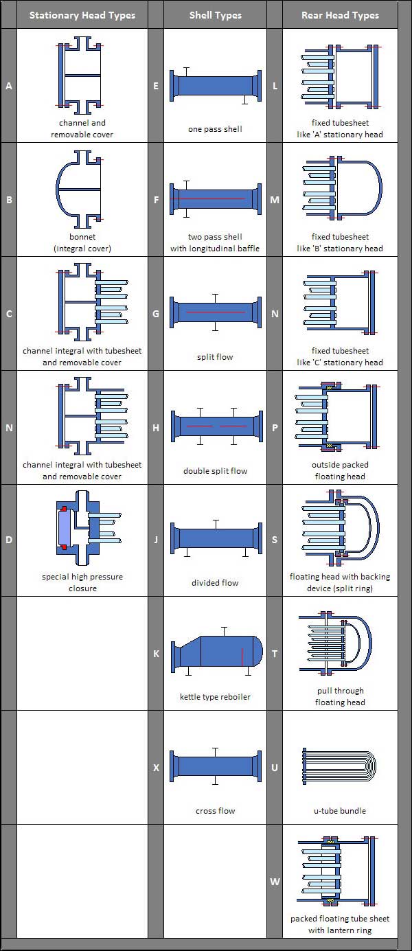
Because of the number of variations in mechanical designs for front and rear heads and shells, and for commercial reasons, TEMA has designated a system of notations that correspond to each major type of front head, shell type and rear head. The first letter identifies the front head, the second letter identifies the shell type and the third letter identifies the rear head type.
Removable bundle exchangers
Removable bundle exchangers give the customer the ability to replace the tube bundle without replacing the shell or Bonnets. They are generally less cost effective than non removable designs.
BEU/AEU- U Bundle Exchangers are generally the most cost effective design style of removable bundle exchanger. Tubes may be water blasted, steam or chemically cleaned. These units must have an even number of tube passes, sometimes limiting their applicability to a service(e.g. they generally can not be used when a temperature cross occurs).
CEU- This design has the tubesheet welded to the Bonnet. You can remove the bundle from the shell, however to replace the bundle, the inlet Bonnet is included or you must cut off the tubesheet. Tubes may be chemically cleaned, water blasted or steam cleaned.
BEW/AEW- These are straight tube units with one floating head and one stationary head. The floating head is generally sealed with an O-Ring. These units are most often used as oil coolers or air coolers. Cleaning can be performed by either a chemical, mechanical method, water blast or steam cleaning.
AEP/BEP- These are straight tube units with one inside packed floating head and one stationary head. The floating head is generally sealed with packing. These units are most often used as intercoolers and aftercoolers with the gas on the tube side. They are also the most common style for oxygen service exchangers. These units have been used in services with tube side design pressures in excess of 2000 PSIG.
AES/AET- These units are the most expensive of the removable bundle designed units. The floating head is internal to the shell. Tubes can be cleaned mechanically , chemically, water blasted or steam cleaned. The design of these units forces an even number of tube side passes therefore they suffer the same service restrictions as U bundles. Although in theory one pass unit can be designed, this is rarely done. These units are generally used in services where U bundles are not desired and the service may be too corrosive/damaging to the packing used in AEP/BEP units.
- Aerial Tube Bundle Extractor
- Self propelled bundle extractor
- Truck Mounted Bundle Extractor
- Combi Lifter Bundle Extractor
Heat Exchanger TEMA type AES with Floating Head
Part Names
- Stationary Head-Channel
- Stationary Head-Bonnet
- Stationary Head Flange Channel or Bonnet
- Channel Cover
- Stationary Head Nozzle
- Stationary Tubesheet
- Tubes
- Shell
- Shell Flange Stationary Head End
- Shell Flange Rear Head End
- Shell Nozzle
- Shell Cover Flange
- Floating Tubesheet
- Floating Head Cover
- Floating Head Cover Flange
- Floating Head Backing Device
- Tierods and Spacers
- Transverse Baffles or Support Plates
- Impingement Plate
- Vent Connection
- Drain Connection
- Instrument Connection
- Support Saddle
- Lifting Lug
- Pass Partition
Heat Exchanger - Floating Head type
Non removable bundle exchangers
These types of units are often used in high pressure services and services where you wish to avoid leakage problems at gasketed joints. Another advantage is that they are generally more cost effective than removable bundle designs.
NEU- The most cost effective design available. The tubesheet is welded to both the shell and Bonnet. There is no access to the shell. Tubes may be chemically cleaned, water blasted or steam cleaned from inside only. These units are commonly used in high pressure services (such as feedwater heaters), where process conditions allow for even pass exchangers.
NEN- Tubesheets are welded to both the Shell and Bonnets. Access to the tubes is through covers on the channels. These units are favored in very high pressure designs as their construction minimizes the tubesheet thickness and number of high pressure retaining flanges.
AEM/BEM/AEL-Shell side is completely welded up, however, the Bonnets are removable. Chemical, mechanical, and water blast cleaning of the tubes is possible, however you do not have access to the shell.
You should avoid using Steam cleaning on a fixed tube sheet unit unless the unit has a shell side expansion joint. The steam will cause the tubes to expand and pull out of the Tube Sheet causing failure at startup.
Differential thermal expansion
Since the duty of Heat Exchangers includes the handling of fluids of differing temperature, flow
rate and thermal properties, differential expansion of the metals will take place.
When the terminal temperature difference between the fluids is substantial, over 50-60 degrees,
these stresses can become severe, causing shells to become deformed and damage mounting supports,
tubes to deform the tube sheet or tubes to become broken or dislodged from the tube sheet.
Fixed tube sheet designs are most vulnerable to differential thermal expansion, because there is
no inherent provision to absorb the stresses. One approach in common use is installing an expansion
joint in the shell pipe of such designs. This is a cost effective approach for pipe-size shells.
An expansion joint can also be installed in the tube side of floating head designs, but manufacturing
costs are much higher.
Diagram of U-Tube Heat Exchanger
Alternative approaches involve the design of a U-tube bundle so that each tube can inpendently expand and contract as needed or by using a rear floating internal tube sheet design which allows the entire bundle as a unit to expand and contract. The floating head is typically sealed against the interior of the shell by means of packing or O-ring designs.
U-tube designs while offering the best answer for differential thermal expansion, have some drawbacks. Individual tubes can be difficult of expensive to replace, especially for interior tubes. Also, the tube interior cannot be effectively cleaned in the u-bends. Erosion damage is also frequently seen in the u-bends in high tube side velocity applications. In large diameter shells, the long length of unsupported tube in the u-bends of outer tubes can lead to vibration induced damage.
Floating head designs of head exchangers
In an effort to reduce thermal stresses and provide a means to remove the tube bundle for cleaning,
several floating rear head designs have been established.
The simplest is a "pull-through" design which allows the tube bundle to be pulled entirely
through the shell for service or replacement. In order to accomodate the rear head bolt circle,
tubes must be removed resulting in a less efficient use of shell size. In addition, the missing
tubes result in larger annular spaces and can contribute to reduced flow across the effective tube
surface, resulting in reduced thermal performance. Some designs include sealing strips installed
in the shell to help block the bypass steam.
Another floating head design that partially addresses the above Disadvantages is a "split-ring
floating head". Here the floating head Bonnet is bolted to a split backing ring instead of the
tube sheet.
This eliminates the bolt circle diameter and allows a full complement of tubes to fill the shell.
This construction is more expensive than a common pull through design, but is in wide use in petrochemical
applications. For applications with high pressures or temperatures, or where more positive sealing
between the fluids is desired, the pull-through design should be specified.
Two other types, the "outside packed lantern ring" and the "outside packed stuffing
box" designs offer less positive sealing against leakage to the atmosphere than the pull though
or split ring designs, but can be configured for single tube pass duty.
Shell constructions
The most common TEMA shell type is the "E" shell as it is most suitable for most industrial
process cooling applications. However, for certain applications, other shells offer distinct advantages.
For example, the TEMA-F shell design provides for a longitudinal flow plate to be installed inside
the tube bundle assembly. This plate causes the shell fluid to travel down one half of the tube
bundle, then down the other half, in effect producing a counter-current flow pattern which is best
for Heat Transfer.
This type of construction can be specified where a close approach temperature is required and when
the flow rate permits the use of one half of the shell at a time. In heat recovery applications,
or where the application calls for increased thermal length to acheive effective overall Heat Transfer,
shells can be installed with the flows in series.
Up to six shorter shells in series is common and results in counter-current flow close to performance as if one long shell in a single pass design were used.
TEMA G and H shell designs are most suitable for phase change applications where the bypass around the longitudinal plate and counter-current flow is less important than even flow distribution. In this type of shell, the longitufinal plate offers better flow distribution in vapor streams and helps to flush out non-condensables. They are frequently specified for use in horizontal thermosiphon reboilers and total condensers.
TEMA J Shells are typically specified for phase change duties where significantly reduced shell
side pressure drops are required. They are commonly used in stacked sets with the single nozzles
used as the inlet and outlet.
A special type of J-shell is used for flooded evaporation of shell side fluids. A separate vapor
disengagement vessel without tubes is installed above the main J shell with the vapor outlet at
the top of this vessel. The TEMA K shell, also termed a "Kettle Reboiler" is
specified when the shell side stream will undergo vaporization.
The liquid level of a K shell design should just cover the tube bundle, which fills the smaller
diameter end of the shell.
This liquid level is controlled by the liquid flowing over a wier at the far end of the entrance
nozzle. The expanded shell area serves to facilitate vapor disengagement for boiling liquid in the
bottom of the shell. To insure against excessive liquid carry-though with the vapor stream, a separate
vessel as described above is specified.
Liquid carry-through can also be minimized by installing a mesh demister at the vapor exit nozzle.
U-bundles are typically used with K shell designs. K shells are expensive for high pressure vaporization
due to shell diameter and the required wall thickness.
The TEMA X shell, or crossflow shell is most commonly used in vapor condensing applications, though it can also be used effectively in low pressure gas cooling or heating.
It produces a very low shell side pressure drop, and is therefore most suitable for vacuum service condensing. In order to assure adequate distribution of vapors, X-shell designs typically feature an area free of tubes along the top of the exchanger. It is also typical to design X shell condensers with a flow area at the bottom of the tube bundle to allow free condensate flow to the exit nozzle. Careful attention to the effective removal of non-condensables is vital to X-shell constructions.
Other Pages about Heat Exchangers
Related Post(s)
The floating-head heat exchanger is a type of tube heat exchanger in which the tube sheet combination is independent and can move freely within the shell...