 |
Centrifugal Pump |
Centrifugal Pumps has been designed specially for use in the food, dairy, beverage, pharmaceutical and light chemical industries. Centrifugal pumps including multi-stage designs and those for high inlet pressure, can handle most low viscosity applications. Centrifugal pumps can provide the most cost effective solution. Attributes include..
high efficiency
low power consumption
low noise level
low NPSH requirement
easy maintenance
Principle of operation
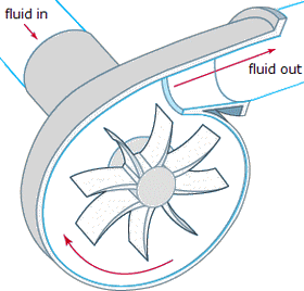
Fluid is directed to the impeller eye and is forced into a circular movement by the rotation of the impeller vanes. As a result of this rotation, the impeller vanes transfer mechanical work to the fluid in the impeller channel, which is formed by the impeller vanes. The fluid is then pressed out of the impeller by means of centrifugal force and finally leaves the impeller channel with increased pressure and velocity. The velocity of the fluid is also partly converted into pressure by the pump casing before it leaves the pump through the outlet.
The principle of the multi-stage centrifugal pump is the same as the conventional centrifugal pump. The pump consists, however, of several impellers (several stages) which increase the pressure from one stage to another but flow rate is unchanged. The multi-stage centrifugal pump operates as if several conventional centrifugal pumps are connected in series.
Operation of a Centrifugal Pump
Parts of Centrifugal Pumps
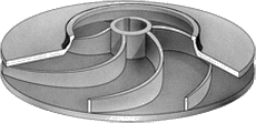
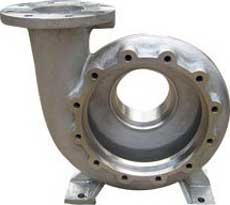
In general centrifugal pumps does not contain many parts, with the pumphead being connected to a standard electric motor. The impeller is fixed onto the pump shaft which is housed in a pump casing and back plate - these components are described below..
Back Plate
The back plate is of pressed steel manufacture, which together with the pump casing form the actual fluid chamber in which the fluid is transferred by means of the impeller.
Mechanical Seal
The connection between the motor shaft/pump shaft and the pump casing is sealed by means of a mechanical seal.
Shroud and Legs
Most pump types are fitted with shrouds and adjustable legs. The shroud is insulated to keep noise to a minimum and protect the motor against damage.
Maintenance Tip.. How to Install a Packing Gland
Pump Shaft/Connections
Most pumps have stub shafts that are fixed to the motor shafts by means of compression couplings, eliminating the use of keyways. The stub shaft assembly design provides a simple, yet secure method of drive that reduces vibration and noise. On the multistage centrifugal pump the length of the pump shaft will differ depending upon the number of impellers fitted.
Adaptor
Most pumps are fitted with a standard IEC electric motor. The connection between the motor and back plate is made by means of an adaptor, which can be attached to any standard IEC or C-frame electric motor.
Pumps supplied with direct coupled motors have no adaptors.
Related Post(s)

Cavitation in pumps is the rapid creation and subsequent disintegration of bubbles in a liquid. Bubbles may not seem very powerful, but...