 |
Brinell Hardness Testing |
Hardness is a characteristic of a material, not a fundamental physical property. It is defined as the resistance to indentation, and is determined by measuring the permanent depth of indentation. Put more simply, when using a fixed force (load) and a given indenter, the smaller the indentation, the harder the material.
Indentation hardness value is obtained by measuring the depth or the area of the indentation using different test methods.
The Brinell hardness test method as used to determine Brinell hardness is defined in ASTM E10. It is typically used to test materials with a structure or surface too coarse to be tested by any other test method, for example castings and forgings. Brinell tests often use a very high test load (3000 kgf) and a 10mm diameter indenter so that the resulting indentation eliminates most surface and subsurface irregularities.
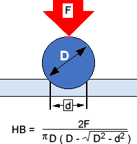
In the Brinell method, a predetermined test load (F) is applied to a carbide ball of fixed diameter (D) which is held for a predetermined time and then removed. The resulting impression is measured with a specially designed Brinell microscope or optical system over at least two diameters - usually perpendicular to each other - and these results are averaged (d). Although the calculation below can be used to generate the Brinell number, a graph is usually used to convert the average diameter measurement into a Brinell hardness number.
Common test forces range from 500kgf, often used for non-ferrous materials, to 3000kgf, usually used for steel and cast iron. There are other Brinell scales with loads as low as 1kgf and intrusions as small as 1mm in diameter, but these are not commonly used.

Test Method Illustration
D = Ball diameter
d = impression diameter
F = load
HB = Brinell result
The biggest source of error in Brinell tests is the measurement of indentation. Due to differences between the operators making the measurements, the results will vary even under perfect conditions. Under less than perfect conditions, the variation can be greatly increased. Often the test surface is prepared with a grinder to remove the surface condition.
The jagged edge complicates the interpretation of the indentation. In addition, when operators know the specification limits for rejects, they can often be influenced to view the measurements in a way that increases the percentage of "good" tests and reduces retesting.
Over the years, two types of technological solutions have been developed to combat the problems associated with Brinell measurement errors. Automatic optical Brinell scopes, such as the B.O.S.S. system, use computers and image analysis to read notches in a consistent manner. This standardization helps eliminate operator subjectivity, so operators are less inclined to automatically view in-tolerance results when the sample result may be out-of-tolerance.
Brinell units, which measure according to ASTM E103, measure samples using Brinell hardness parameters combined with a Rockwell hardness method. This method offers the most repeatable results (and greater speed) because the vagaries of optical interpretation are eliminated by the use of an automatic mechanical depth measurement.
However, the results of this method may not be strictly consistent with those of Brinell because of the different test methods - some materials may require compensation of results. It is easy to establish the correct values in those cases where this may be a problem.
Reference(s) ..www.hardnesstesters.com
Basic principle and practical procedure of the Brinell hardness test
OTHER TESTS OF (HARDNESS)

