Flange Weld Tester |
The Flange Weld Tester is used to hydrotest the integrity of new welds where a Weld(ing) Neck or Slip On flange has been added to a pipeline.
When a new flange has been welded to a pipeline, traditionally the method used
to prove the integrity of a weld would involve flooding the pipeline in order to hydrotest. This
is time consuming and costly, and often it is impossible, to fill a whole pipe system with e.g.
demineralised water.
The Flange Weld Tester overcomes this problem, because he creates a chamber around the weld and
only that chamber is tested.
The images below should clarify the method of a Flange Weld Tester.
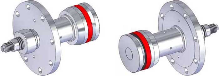
Fig. 1
Fig. 1 shows the Flange Weld Tester. The tool are designed with a single seal and flange configuration and are available in a range of sizes compatible with common pipe schedules and flange types/sizes. Size range.. common pipe sizes NPS 1/2-24 as standard, specially configured tools in sizes up to NPS 48 may be engineered and designed for specific applications. Designed to provide recommended test pressure requirements up to ASME Pressure Class 2500.
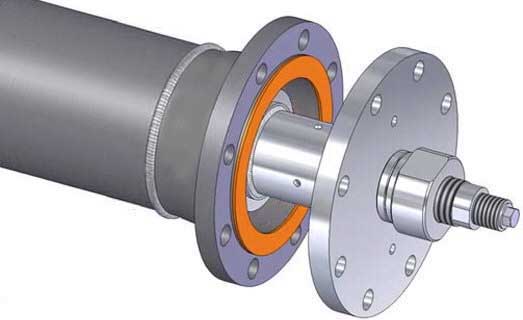
Fig. 2
Fig. 2 shows that the Flange Weld Tester is inserted into the pipe, with a gasket between the two flanges.
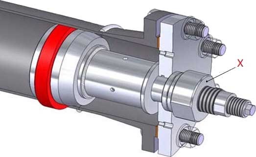
Fig. 3
Fig. 3 shows a cross section where the Flange Weld Tester is inserted into the pipe (flange bolts are hand-tightened). Nut (X) is tightened, causing the sealing ring (red color) has been expanded. Flange bolts can now be put to the correct torque.
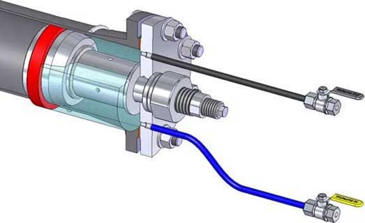
Fig. 4
Fig. 4 shows a typical setup for a hydrostatic pressure test. At the lowest point, the chamber filled with water, until at the highest point the water flows out, and hence the chamber is bleeded.
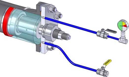
Fig. 5
Fig. 5 shows a typical arrangement for a hydrostatic pressure test. At the top a pressure gauge is installed, and depending on customer's specification, the pressure must remain a certain time, usually between 10 and 60 minutes.
The test is typically undertaken using water as the test medium, but can be undertaken using inert gas where necessary. The test undertaken is normally a strength test of the joint at 1.5 times the design pressure, but can also be used as a leak testing means, typically undertaken at 1.1 times the design pressure.
If the pressure test was positive, the chamber can be depressurized, and the Flange Weld Tester can be removed.
Remark(s) of the Author...
Attention Point
When using a Weld(ing) Neck flange, the weld seam on the inside of the pipe has a height of a few millimeters. Before the flange weld tester is mounted, this so-called penetration weld must be removed using, for example, a grinding machine, because otherwise the Flange Weld Tester might not be able to be inserted into the pipe.
In the past, I have often used this test method.
In all cases, it was a matter of cost saving, but also because when it was not permitted to fill
the entire pipe system with water.
Related Post(s)
In-Line Weld Test Tools provide a fast and efficient method of verifying the integrity of butt welds joints or other welded pipe components...