 |
Reference Points |
Location is Relative
An object's location is always given relative to another reference object.
For example, the location of a Heat Exchanger may be described as five blocks from the General
Service Building. To be more specific, the Heat Exchanger is four blocks east and three blocks south
of the General Service Building. With this illustration, a direction and a distance from the General
Service Building has been established.
Several things are assumed to be known, the place to begin (General Service Building), and understanding of east and south (reference directions), and the length of a block (unit of displacement). Without consensus on these things, communication of the location of a Process Plant becomes unclear.
Before beginning with making drawings for a new process plant or building, there must be determine
where the new building in the area will take his place. A coordination system, which refers to an
officially recognized point therefore is necessary.
In the Netherlands, for example, are thousands of official reference points, distributed across
the country ...search on the Internet on geographic coordinate conversion, triangulation stations,
benchmarks, geography or topography. You'll find a lot of information about how reference points
are measured and identified.
Horizontal Reference
Defining a starting point of the site related to the North / South direction, is one of the first
steps in setting up a coordination system.
In principle, with a simple reliable compass the direction of the magnetic north can to be determined.
In the image below the true north is at 18°. As a draftsman would work with the true north
coordinates, he will immediately find out that each line from west to east and from north to south
at an angle of 18° must be drawn.
To avoid this, a Plant North will be determined. In the example below, the true north, 18° is
reversed, draftsmen and construction contractors will be grateful for it.
General there will be tried, to approach the true north-south coordinates as close as possible.
A rule is, that the angle between true north and Plant North can not exceed 45°. At 50°,
for example, the Plant North would be on the right side, so on the Eastern side of the image.
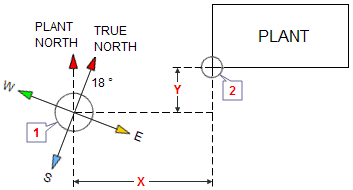
1 = Official reference
point
2 = South West angle of new plant
X = East West distance from new plant to reference point
Y = North South distance from new plant to reference point
Vertical Reference
Before starting with any building, the site is leveled (graded), what means that the ground is
made as flat as practically possible. After leveling we talking about "finished grade",
where the highest graded point is termed "high point of finished grade".
This highest point of finished grade refers to an official reference point on which all vertical
measurements are related. In the Netherlands, for example, many vertical measurement are in relation
to the "Normaal Amsterdams Peil" (NAP). If the field compared to the NAP is 1 meter higher,
usually the reference point will not become a zero start of 1000 mm, but in this case a zero start
at zero(0).
On a isometric view of a pipe line elevations are indicated by EL.109665 or EL.99450 etc..
What is meant by this vertical dimensions?
- The first EL.109665 you can read as.. centerline of pipe is 9665 mm above zero point
- The second EL.99450 you can read as.. centerline of pipe is 550 mm below zero point
Well, the vertical zero point in this case is 100 meters (100000 mm), and this has the advantage that no negative (minus) values on drawings need to be applied.
Remark(s) of the Author...
Center-Line and Elevation symbol
I have learned, to apply a Elevation symbol and a Center-Line symbol to a isometric.
Namely, the Center-Line symbol at the end of the centerline, and ON that line
the Elevation symbol, followed by the elevation-numbers.
| The sign on the left shows the centerline symbol. Tip for AutoCad users.. use the CDT font, lower case Q. |
|
| The sign on the left shows the Elevation symbol. That sign, you will see on almost every isometric. |
A combination of both signs, you see rarely nowadays on an isometric. Usually only the Elevation
symbol is applied. Why? there are many reasons to make no old-fashioned isometrics.
Large-engineering companies can tell you why!
Related Post(s)
A Plot Plan is a scale drawing that gives an overview (top view) of the entire plant...