 |
Piping Arrangement |
Views in Piping Drawings
There are two types of views in hand-drawn piping drawings..
- Orthographic - Plans and Elevations
- Pictorial - Isometric Views
Orthographic drawings are views (front, side, top etc.) of an piping system, and in Piping they are called "Piping Arrangements".
An orthographic view shows only one side, and therefore multiple drawings (views) are necessary to show a complete Piping Arrangement.
In complex systems, where orthographic views do not illustrate the details of the design, pictorial view in isometric presentation is made for clarity.
Priorities on a Piping Arrangement
Process equipment and piping have priority on the Piping Arrangement. The major primary beams and secondary beams are also shown, even as Utility stations so that the most efficient route for utilities can be determined.
Order of importance of pipe lines in a Piping Arrangement..
- Alloy steel and other special materials
- Large bore piping
- High temperature/high pressure piping
- Lined piping
- Carbon Steel Process Piping
- Utility piping
Further (if possible) all equipment, instrument connections, with the tag numbers will be shown on a Piping Arrangement. Important details are often in a larger scale in the same drawing shown.
Even as a Plot Plan, a whole process plant usually can not be given on a readable drawing. Therefore the Piping Arrangement show parts of a process plant.
Types of Piping Arrangement Drawings
Pipelines on a Piping Arrangement are shown by single lines and double lines.
In single line representation only the center line of the pipeline is drawn using a solid line. In double line representation the actual size to scale is drawn with center line marked in chain-dotted lines.
Single lines representation
- Flanges are shown as thick lines drawn to the scaled outsite diameter of the flange.
- For flanged joints a small gap between dimension lines will be shown to indicate a gasket.
- Valves are shown with identification number and a handwheel is drawn with stem fully extended. If a valve is lever operated, then the movement of handle position is given.
- Dimensions for flanged valves are given to the flange faces, while non flanged valves are dimensioned to the center lines of their stems.
Double line presentation
Single line presentation
Example of a single line Piping Arrangement
The drawing shows 2 pumps, 4 valves (all Handwheel operated and flanged), a pipe line and a column.
The line number CD - PL - 101 - 12 - C300 - T2 - I2 tells something about the pipe line.
| CD | Indicator for plant or system, where the pipeline is located. |
| PL | Indicator for a service designation. |
| 101 | Indicator for the serial number of the pipe line. |
| 12 | Indicator NPS, in this case the main pipeline is NPS 12. |
| C300 | Indicator for Pipe Line Class or "Pipe Spec". C tells that the material is Carbon Steel, and 300 indicates the Pressure Class. |
| T2 | Indicator for E-tracing type. |
| I2 | Indicator for Insulation type. |
Above description of the line number is only an example. For line numbers are no standard definitions, and therefore a customer specification can be different from what is here defined.
The indication 12-314 (Typ) on the valve told that the valve is 12 inches and 314 indicates the type of valve. The same applies also to the valve near the pump, where DR indicates a Drain Valve.
Typ stands for Typical and means that there is another ore more valves in that drawing with the same specification. The advantage of this indicator is, that items with the same specification only once need to be defined.
Furthermore, the red arrow indicates the flow direction, which perhaps is unnecessary, because the pipe line is connected to the Suction side of the pump.
- Dis. = Discharge, pressure side of a pump
- Suc. = Suction, suction side of a pump
An important item is designation TF (Top Flat) which is shown to the eccentric reducer at the pump. That means that the flat side of the reducer is on the top of de pipe line. If it was vice versa BF (Bottom Flat), also the elevation to the suction side of the pump must be given.
Example for the pump suction side..
A eccentric reducer 12 to 8 inch has a center-line difference from 52.4 millimeters.
(12" = O.D. 323.9 mm / 8" = O.D. 219.1 mm / Length = 203 mm / Center-line difference = 52.4 mm).
If the reducer bottom flat, an elevation round off upwards EL.100548 must be shown.
Note.. The connection to the column is Class 600. This change in Pressure Class is indicated
by a so-called "Spec break" (change of Piping Class Specification). In this case it means, that the flange that connect to nozzle C1 also must be have a Pressure Class of 600, and that the material probably not changed.
Another important item is the elevation (given in red) of nozzle C1 from the column. The elevation EL.104966 is shown, because the pipe line ends with an eccentric reducer Bottom Flat (BF). In this case it means, that the vertical centerline from nozzle C1 is 15.88 mm above the center line of the pipeline.
A eccentric reducer 14 x 12 (355.6 mm x 323.9 mm) has a length of 330 ,mm and a center-line difference from 15.88 mm.
Symbols on a Piping Arragement Drawing
On the drawing can be seen that the pipe line(s) from the pumps run up to the column. The pipeline starts with elevation EL.100600 at the pump suction site and ends at elevation EL.104950 at nozzle "C1" from the column. But without the elevations, the upward routing is also visible.
For single line representation there are a lot of symbols, which illustrate a directional change.
The three partly open blue circles in the drawing, indicate three Elbows which are bending down.
The two blue half-moons around the pipelines/valves indicate that the valves are at the bottom of the pipeline are located. The two valves are needed to drain the pipeline. By applying eccentric reducers (Top Flat) in the lowest part of the pipeline, the two valves make it possible to fully empty the system.
In the main Menu "Docs" the most used drawing symbols can be found.
3-Dimensional View
More and more engineering companies show Plot Plans, equipment and piping arrangements in a 3D view. Better 3D software has made this possible, and generally has this way of drawing many advantages.
There are many programs that can be made 3D views, but they are all very expensive. Large engineering companies often have developed their own software. Some of these programs make it possible "to walking through a whole plant" in order to find a particular item. It is very impressive, what is possible with that type of software.
Summary
A standard Piping Arrangement does not exist.
Like a Plot Plan or Equipment Arrangement, in the development phase of a new plant, the requirements for the drawings will be made by customer and/or engineering company.
Remark(s) of the Author...
My own experience with 3-Dimensional Views...
Since 1999, I draw many topics in 3D views.
The reason is, that I have noted that a pipefitter or construction worker knows immediately what he must build. Another reason is, that people who are not able to read a drawing, also know what I am trying to explain.
For myself, I discovered that it cost me less time, to make different views, because with acceptable 3D software, each view (what ever you want) in seconds can be displayed and printed.
My first 3-D drawing
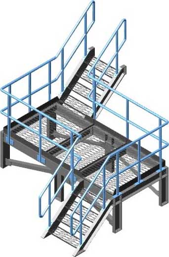
In recent years I have found a combination of both, Orthographic and 3D view. If it is a simple drawing I show only two or three orthographic views. In complex drawings I show the necessary orthographicthis views with in the right corner of the drawing, a 3D view. It works perfectly for those who must carry out the job.
Simple drawing of a 3-Dimensional view from the Piping Arrangement above mentioned.
The 3D view from the Piping Arrangement is simple but it probably shows, for most users, a direct understandable drawing.
At the end of 2008 I had a job for the design of a new 14 inch pipeline from and between two storage tanks. Normally I had made isometric views from the new pipe line and orthographic views of the supports. But in that case, for the first time, I made only 3d views to scale from the pipeline, valves, supports etc.. I gave the pipefitters and construction workers all possible views...the job is performed without any problems.
With respect to our "grandfathers", they builded without our current techniques, the largest plants on earth.
Related Post(s)

The Piping and Instrument Diagram (P&ID) provides a schematic representation of the piping, process control, and instrumentation....