Piping Fabrication Tolerances |
Piping prefabrication is an important step in the construction of piping systems. Whenever feasible, sections of piping systems or piping spools are prefabricated by the contractor in the workshop. After prefabricating the spools, they are transported to the field and assembled to complete the piping system.
Field assembly of pipeline sections involves alignment, assembly, welding and bolting of flange connections, including valves, special parts and instrumentation. Pipeline spools must be fabricated within certain tolerance levels to ensure that the final assembly meets pipeline design requirements.
If the required manufacturing tolerances are not adhered to, there is the potential for undesirable stresses to be imposed on the piping systems during on-site assembly. Imposing additional stresses on the piping system during the fabrication phase invalidates the design assumptions and can lead to unpredictable behavior of the system during operation and, in some cases, failures with catastrophic consequences.
Chapter V of ASME B31.3 contains requirements for the fabrication, assembly and mounting of metal piping for normal use.
ASME B31.3 defines fabrication as the preparation of pipelines for assembly, including cutting, threading, grooving, forming, bending and joining parts into subassemblies. Fabrication can be performed in the factory or in the field.
- Linear tolerances
- Angular and rotational tolerances
The section below describes the various fabrication tolerances that must be maintained on prefabricated piping assemblies in a production shop.
Internal and external misalignment in circumferential welds
Ends of pipe or pipe-to-flange or fitting connections must be accurately aligned. Internal criteria for misalignment are defined in section 328.4.3 of ASME B31.3.
- NPS 24 and smaller pipe-to-pipe or pipe-to-fitting: maximum misalignment of 1.6 mm
- NPS 26 and larger pipe-to-pipe or pipe-to-fitting: maximum deviation of 3.2 mm if allowed
Tolerances on linear sizes

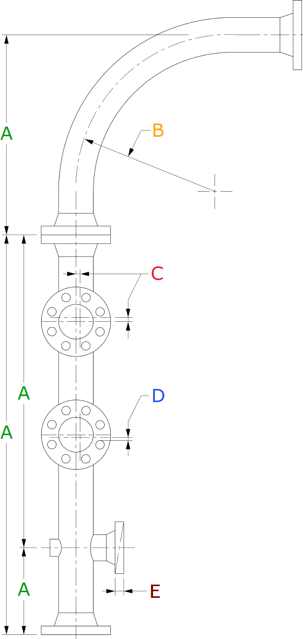
A Variations in the indicated dimensions for Center to Face. Location of attachments etc, shall not exceed 3 mm. (Tolerance shall be cumulative)
B For Piping Bends having a radius equal to SIX times the diameter or larger variations in the finished pipe caused by bending including any folds and bulges shall not exceed ± 3% x Nominal Ø of the Pipe.
C Lateral translation of flanges in any direction from the indicated position shall not exceed 1.5 mm.
D Rotation of flanges from the indicated position as shown shall not exceed 1.5 mm.
E Aligment of flanges shall not deviate from the indicated position measured across any diameter more than 0.75 mm.
Tolerance on Flanges
Pipe flanges are oriented so that the bolt holes are horizontal (north/south of the plant) when the flange face is horizontal and vertical centerlines when the flange face is vertical.
Rotation of flanges, measured as the offset between the height of bolt holes on either side of a flange centerline, shall not exceed ±1/16 in or ±1.6 mm. In addition, the tilt of a flange measured at the circumference over any diameter shall not exceed 2.5 mm/m or ±1/32 in or ±0.8 mm from the square position.

Tolerances on pipe spools for field adjustment
When field adjustment is required, it is recommended that one spool have a straight end that is 100-150 mm (4-6 inches) longer than the dimension shown on the pipe drawing for on-site adjustment.
The installation contractor shall verify the dimensions on site before trimming and beveling the spool with cutting allowance. The contractor shall make provision in the material removal for these over-lengths (cut allowance).
The adjacent spool is prepared in the shop with a chamfered end and need not have overlengths for field adjustment.
Reference Standards
- Pipe Fabrication Institute Standard PFI ES3
Fabricating Tolerances - Pipe Fabrication Institute Standard PFI ES-24
Pipe Bending Methods, Tolerances, Process and Material Requirements