Reinforced Branch Connection Set-On type
Where a Reinforced Branch Connection is required?
With large pipe dimensions, it is customary, to form a TEE intersection by cutting a hole in the straight run (the header) and welding in the leg perpendicular (the branch), this is called a STUB-IN.
Similarly, nozzles are installed on pressure vessels by cutting a hole in the side of the vessel and welding in an appropriately sized pipe to form the nozzle. These intersections ensure a 'hole weakening' on the vessel or piping system, due to the metal removed and the stress concentration created.
In critical systems, this weakness must be compensated, and can be restored with a Reinforcing Pad, to strengthen the piping branch connection or the pressure vessel nozzle.
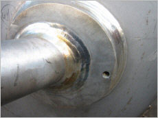
Branch Connection with Reinforcing Pad (Set-On type)
Dimensions Reinforcing Pad
For the dimensions of a Reinforcing Pad you can handle as rule..
- Material = same material as the run pipe
- Width = half a diameter of the branch pipe (at least 50 mm)
- Thickness = same thickness as the run pipe, with a min. of 3 mm and a max. of 20 mm
However, it is customary for most companies a so-called Branch table handling. This document defined the methods, which must be applied, if a branch (with or without a Reinforcing Pad) in a run pipe must be made. It is also usually present a specification that defines own dimensions, because each company has their own criteria. (e.g. type of product, pressure and temperature, national regulations, local markets)
Installation of Reinforcing Pad
Example for the assembly of a Reinforcing Pad.
- Determine the location of the branch, and make a round hole in the run pipe where the diameter should be equal to the inside diameter of the branch.
- Finish the branch equal to outside diameter of run pipe and make a welding bevel of around 30°.
- Place the branch with a gap by about 3 to 4 mm about the hole location on the run pipe, and tack weld the branch on a sufficient number of places. Then the new branch can be completely welded.
- If de weld is ready, depending on the requirements Non Destructive Examination (NDE) must be done.
- Then the Reinforcing Pad can be placed by slide him over the branch. The pad must be positioned so that around the branch, is overall the same open space, and that the pad is fully in line with the run pipe. Tack weld the pad on a sufficient number of places, and after that the pad can be inside and outside fully welded; depending on the prescribed quality requirements, then again NDE must be done.
- Attention! -- Cited as a flange at the branch pipe is welded, you must obviously make sure that the ring is placed earlier. You will not be the first and probably not the last, with a Reinforcing Pad in his hands, and discovered that the sequence of action was not entirely correct.
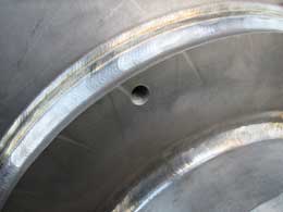
Weep-Hole
On a number of images, you might be have seen a round hole in the Reinforcing Pad. This is
a 'Weep Hole' and may have multiple functions. Sometimes also called Tell Tale hole or Vent
hole.
Opinions about the use of this hole varies, and therefore I give 2 possible uses of a weep hole..
By threading the hole, a test gauge can be thread for a 'air/soap' test to check for leakage. The
thread, mostly1/4" NPT will be used.
Weep holes serves as a vent during welding for entrapped gasses and prevents the Reinforcing Pad from becoming a 'jacketed' vessel.
Weep holes in Reinforcing Pads shall be sealed upon completion of pressure test.
NPT is the best known and most widely used connection where the pipe thread provides both the mechanical joint and the hydraulic seal. NPT has a tapered male and female thread which seals with Teflon® tape or jointing compound. ASME B1.20.1 covers dimensions and gaging of NPT pipe threads for general purpose applications.
ASME B31.3, in paragraph 328.5.4 says..
A vent hole shall be provided at the side (not at the crotch) of any pad or saddle to reveal leakage in the weld between branch and run and to allow venting during welding and heat treatment.
Related Post(s)
Stub-in and Stub-on connections are two essential techniques used in the pipeline industry to safely connect pipes together...