Pipe Flow Measurement.. Orifice Plates
Why measure Flow?
In many of today's industrial processes, it is essential to measure accurately the rate of fluid flow within a system as a whole or in part. This applies equally to gases and liquids (e.g. carbon dioxide, nitrogen, liquors etc.) which are an integral part of the process, or to compressed air, water or steam which are fundamental to plant operation. The installation of any flowmeter can be justified in one of two ways..
1. Process control
Here the flowmeter is used to measure the rate of fluid or energy flow to allow the process to be
controlled and so ensure that the end product is of the required quality. A common example of this
would be in steam injection systems for the animal feeds industry...too much steam and the product
will not pellet...too little steam and the raw materials will not process and may damage the production
machinery.
2. Cost allocation
Where energy is used to provide process or space heating, it is fundamental to know where the costs
associated with the energy are actually being incurred. Flowmetering allows energy costs to be
allocated to a particular product, department or other user this usually resulting in a significant
reduction in total energy costs.
Understanding Pipe Flow Rate
The term pipe flow rate is often used to refer to flow rate for any closed conduit flow under pressure. The closed conduit is often circular, but may also be square or rectangular, such as a heating duct. The other major category of flow is open channel flow, which occurs when there is a free liquid surface open to atmospheric pressure.
Measurement of the flow rate of a fluid flowing under pressure is carried out for a variety of purposes, such as billing for water supply to homes or businesses, or for monitoring or process control of a wide variety of industrial processes which involve flowing fluids.
Pipe flow measurement is often done with a differential pressure flow meter like the orifice, flow nozzle, and ventruri meter; Orifice Plates are discussed in this article.
For each type, a constriction in the flow path causes a pressure drop across the meter. The pressure drop can be measured and correlated with flow rate.
Why use Orifice plates..
Orifice plates are still the most widely used type of flowmeter in the world today. They offer significant cost benefits over other types of flowmeter, especially in larger line sizes, and have proved to be rugged, effective and reliable over many years. Where a need exists for a rugged, cost effective flowmeter which has a low installation cost and a turndown of not more than 4:1, the orifice plate continues to offer a very competitive solution.
How do Orifice plates work..
An orifice plate installed in a line creates a pressure differential as the fluid flows through it. This differential pressure is measured via impulse lines by a differential pressure transmitter which converts it into an analogue or digital signal which can be processed to provide a display of the instantaneous rate of flow.
The relationship between the rate of flow and the differential pressure produced is very well understood and is fully covered by comprehensive national standards. The relevant standards are BS 1042 and the equivalent ISO 5167. One of the principle advantages of orifice plates manufactured and installed following these standards is that they do not require calibration. This means that orifice plates are very cost effective on larger line sizes.
Orifice Flow System
Note.. Configuration shown in above image is for Steam. Gas and Liquid installations will differ.
Standards for Flow Nozzles, Venturies and Orifices
ISO 5167-3:2003 specifies the geometry and method of use (installation and operating conditions) of nozzles and Venturi nozzles when they are inserted in a conduit running full to determine the flow-rate of the fluid flowing in the conduit.
ISO 5167-3:2003 also provides background information for calculating the flow-rate and is applicable in conjunction with the requirements given in ISO 5167-1.
ISO 5167-3:2003 is applicable to nozzles and Venturi nozzles in which the flow remains subsonic throughout the measuring section and where the fluid can be considered as single-phase. In addition, each of the devices can only be used within specified limits of pipe size and Reynolds number. It is not applicable to the measurement of pulsating flow. It does not cover the use of nozzles and Venturi nozzles in pipe sizes less than 50 mm or more than 630 mm, or for pipe Reynolds numbers below 10000.
ISO 5167-3:2003 deals with two types of standard nozzles, the ISA 1932 nozzle and the long radius nozzle, as well as the Venturi nozzle.
The two types of standard nozzle are fundamentally different and are described separately in ISO 5167-3:2003. The Venturi nozzle has the same upstream face as the ISA 1932 nozzle, but has a divergent section and, therefore, a different location for the downstream pressure tappings, and is described separately. This design has a lower pressure loss than a similar nozzle.
For both of these nozzles and for the Venturi nozzle direct calibration experiments have been made, sufficient in number, spread and quality to enable coherent systems of application to be based on their results and coefficients to be given with certain predictable limits of uncertainty.
BS 1042-1-1.2 standard specifies the measurement of fluid flow in closed conduits. Pressure differential devices. Specification for square-edged orifice plates and nozzles (with drain holes, in pipes below 50 mm diameter, as inlet and outlet devices) and other orifice plates.
Geometry and method of use for conical entrance orifice plates, quarter circle orifice plates and eccentric orifices plates. Also square-edged orifice plates and nozzles outside the scope of BS 1042:Section 1.1.
ASME MFC-3M standard specifies the geometry and method of use (installation and flowing conditions) for orifice plates, nozzles, and Venturi tubes when they are inserted in a conduit running full, to determine the rate of the fluid flowing. It also gives necessary information for calculating flow rate and its associated uncertainty.
It applies only to pressure difference devices in which the flow remains turbulent and subsonic throughout the measuring section is steady or varies only slowly with time and the fluid is considered single-phased. In addition, the uncertainties are given in the appropriate sections of this Standard for each of these devices, within the pipe size and Reynolds number limits which are specified.
It deals with devices for which sufficient calibrations have been made to enable the specification of coherent systems of application and to enable calculations to be made with certain predictable limits of uncertainty. The devices introduced into the pipe are called primary devices. The term primary device also includes the pressure taps and the associated upstream and downstream piping.
All other instruments or devices required for the measurement or transmission of the differential pressures are known as secondary elements, and in combination are referred to as the secondary devices. This Standard covers the primary devices; secondary devices will be mentioned only occasionally.
The following primary devices are covered in this Standard.. (a) orifice plates, which can be used with the following arrangements of pressure taps.. (1) flange pressure taps, (2) D and D/2 pressure taps, (3) corner pressure taps. (b) nozzles.. (1) ASME long radius nozzles. (c) Venturi tubes.. (1) classical Venturi tubes.
This Standard does not pipe or conduit sizes under 50 mm (2 in.) nominal.
This Standard does not apply to ASME Performance Test Code measurements.
The Standard is applicable to measurement of flow of any fluid, (liquid, vapor, or gas).
References
- Spirax-Sarco
- Miller, R.W.. Flow measurement engineering handbook. 3rd Ed. McGraw-Hill Book Co., New York, N.Y.
- USBR. Flow measurement manual. Water resource(s) Publications, LLC. Highlands Ranch, CO.
Remark(s) of the Author...
Baron Kelvin (William Thomson) once said..
"When you can measure what you are speaking about and express it in numbers, you know something about it; but when you cannot measure it, when you cannot express it in numbers, your knowledge is of a meagre and unsatisfactory kind."
Baron Kelvin
In other words, you cannot manage what you cannot measure and nowhere is that more true than in the measurement of flow.
Related Post(s)
Restriction (RO)
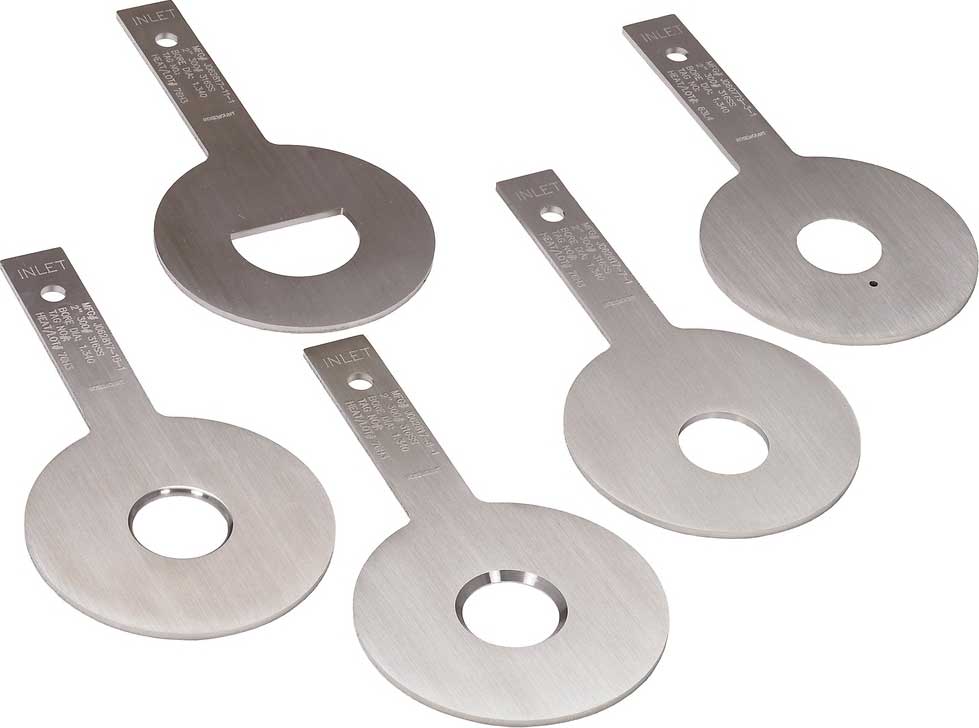
Square Edge (Standard) Bore
Quadrant Edge Bore
Eccentric Bore
Segmental Bore
RTJ and Paddle