 |
Positive Displacement Pump |
A Positive Displacement Pump has an expanding cavity on the suction side of the pump and a decreasing cavity on the discharge side.
Liquid is allowed to flow into the pump as the cavity on the suction side expands and the liquid is forced out of the discharge as the cavity collapses. This principle applies to all types of Positive Displacement Pumps whether the pump is a rotary lobe, gear within a gear, piston, diaphragm, screw, progressing cavity, etc.
A Positive Displacement Pump, unlike a Centrifugal Pump, will produce the same flow at a given RPM no matter what the discharge pressure is.
A Positive Displacement Pump cannot be operated against a closed valve on the discharge side of the pump, i.e. it does not have a shut-off head like a Centrifugal Pump does. If a Positive Displacement Pump is allowed to operate against a closed discharge valve it will continue to produce flow which will increase the pressure in the discharge line until either the line bursts or the pump is severely damaged or both.
Rotary Lobe Pump
As an example, below a Börger Rotary Lobe Pump is described, but there are many more suppliers of these pumps.
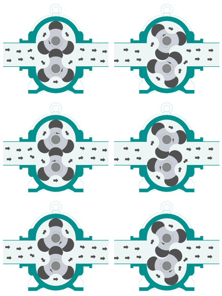
Börger Rotary Lobe Pumps are self-priming, valveless, positive displacement pumps. Two synchronized rotors rotating against each other build chambers towards the pump casing. At the suction side the open chambers fill with the conveyed product. The product is displaced in the direction of the volume flow into the discharge side. The capacity is speed related and the flow is reversible. At standstill the rotors the pump nearly perfect seal.
- Pumping capacity up to 1.000 m3/h (5.300 usgpm)
- Discharge head up to 120 m
Börger Rotary Lobe Pump Glossary
- Block construction
Timing gear in a one-piece construction housing with a strong bearing frame and durable gear wheel pairing. - Compact construction
High performance in a compact design. - Interior pump protection
Protection plates and liners available from a selection of hardened steel, stainless steel, plastic or ceramic. - Life cycle costs
For the customer, capital cost, energy consumption, maintenance and downtime as well as replacement part pricing levels compare excellently with all other displacement pumps. - MIP
Maintenance in Place.. Replacement of wear parts in the blink of an eye, in-situ by service personnel. The way to go in the reduction of maintenance and downtime. - Pump housing
Made from high-quality cast iron, ductile iron, stainless steel or in duplex quality. Thanks to MIP construction an almost limitless operational lifetime is achieved. - Quench
The quench and control liquid filled intermediate chamber, between the pump casing and the timing gear, provides a high degree of safety and is supplied by Börger as standard. - Quick release cover
This is the entrance door to the interior of the pump and provides the quickest possible access to all parts in contact with the pumped medium. - Rotary Lobe Pumps
Self-priming, valveless displacement pumps guarantee pulsation-free and smooth flow patterns; reversible flow by switching the rotation direction. - Rotor materials
Coatings to suit intended usage made from elastomers, plastic, all-metal including stainless steel. - Rotors
The patented rotors with quickly exchangeable tips, elastomer coated or adjustable; scew design for pulsation-free pumping. - Shaft seal
Supplied as standard with strong mechanical seal in different constructions and materials, optional with multiseal or packing. The new DPL size double-acting mechanical seal is especially designed for pumping difficult and hazardous, often viscous media. - Smooth pumping action
Large bucket geometry and short passage through the pump provide a smooth transfer of the pumped fluid.
Gear Pump
In this type of pump, fluid is carried between gear teeth and displaced when they mesh. The surfaces of the rotors cooperate to provide continuous sealing and either rotor is capable of driving the other.
External Gear
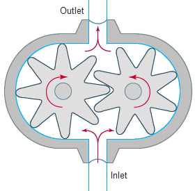
The external gear pump is a positive displacement pump composed of a casing with two meshing gears with external teeth.
One gear is driven by the shaft coupled to a driver. This gear drives the other gear. The rotation of the gears is such that the liquid comes into the inlet port and flows into and around the outer periphery of the two rotating gears. As the liquid comes around the periphery it is discharged to the outlet port. The flow of the pump is regulated by the size of the cavity (volume) between the teeth and the speed of the gears.

Flow from the outlet is further regulated by the amount of liquid that slips back to the inlet port. The amount of slip depends on the side clearance of the gears to the casing, the peripheral clearance of the gear and bore in the casing, gear-to-gear clearance, developed pressure, and viscosity of the liquid. The lower the viscosity, the greater the slippage.
Slippage approaches zero at 5000 SSU. As the viscosity increases, the pump speed is lowered to allow the liquid to fill the space between the rotating teeth.
Most external gear pumps use spur, helical, or herringbone gears. The helical and herringbone gears will deliver more flow and higher pressure. They are quieter than the spur gears but may require more net inlet pressure than a spur gear.
The most common uses for these pumps are to supply fuel oil for burners, gasoline transfer, kerosene, fuel oil, and diesel oil. They are used for hydraulic devices such as elevators and damper controls. They also pump coolants, paints, bleaches, solvents, syrups, glues, lard, greases, asphalt, petroleum, and lube oils and are used in general industrial applications.
External gear pumps can handle small suspended solids in abrasive applications but will gradually wear and lose performance. Materials of construction are dictated by the application and are available in cast iron, ductile iron, bronze, cast steel, and stainless steel. Because of their broad application scope, numerous optional designs are available.
Rated (normal) performance range is 1 to 180 m3/h (5 to 800 gpm), 3.5 to 21 bar (50 to 300 psi), and 0.37 to 75 kW (0.5 to 100 hp). Small external gear pumps frequently operate at four-pole motor speeds (1800 rpm) and have operated at two-pole speeds (3600 rpm). As the pump capacity per revolution increases, speeds are reduced to less than 500 rpm. Operating speeds and flow rates are reduced as the fluid viscosity increases.
Internal Gear
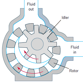
The internal gear pump is a rotary flow positive displacement pump design, which is well-suited for a wide range of applications due to its relatively low speed and inlet pressure requirements.
These designs have only two moving parts and hence have proven reliable, simple to operate, and easy to maintain.
They are often a more efficient alternative than a centrifugal pump, especially as viscosity increases. Internal gear pumps have one gear with internally cut gear teeth that mesh with the other gear that has externally cut gear teeth. Pumps of this type are made with or without a crescent-shaped partition. Either gear is capable of driving the other, and the design can be operated in either direction. Designs are available to provide the same direction of flow regardless of the direction of shaft rotation.

As the gears come out of mesh on the inlet side, liquid is drawn into the pump. The gears have a fairly long time to come out of mesh allowing for favorable filling. The mechanical contacts between the gears form a part of the moving fluid seal between the inlet and outlet ports. The liquid is forced out the discharge port by the meshing of the gears.
Internal gear pumps are commercially available in product families with flows from 1 to 340 m3/h (5 to 1500 gpm) and discharge pressures to 16 bar (230 psi) for applications covering a viscosity range of 2 to 400,000 cSt (40 to 2,000,000 SSU). Internal gear pumps are made to close tolerances and typically contain at least one bushing in the fluid. They can be damaged when pumping large solids. They can handle small suspended solids in abrasive applications but will gradually wear and lose performance. Materials of construction are dictated by the application and include cast iron, ductile iron, bronze, cast steel, and stainless steel.
Small internal gear pumps frequently operate at four-pole motor speeds (1800 rpm) and have operated at two-pole speeds (3600 rpm). As the pump capacity per revolution increases, speeds are reduced. Larger internal gear pumps typically operate below 500 rpm. Operating speeds and flow rates are reduced as the fluid viscosity increases.
Pinion-drive internal gear pumps are a distinctive subclass with unique operating characteristics. They are typically direct-drive arrangements operating at two-, four-, and six-pole speeds for flows below 750 L/min (200 gpm) on clear to very light abrasion, low-viscosity, hydrocarbon-based fluids. They are available in single or multistage module designs capable of pressures to 265 bar (4000 psi).
Internal gear pumps are applied in petrochemical, marine, terminal unloading, asphalt, chemical, and general industrial applications for transfer, lubrication, processing, and low-pressure hydraulics handling a wide range of fuel oils, lube oils, and viscous chemicals (both corrosive and noncorrosive). Because of their broad application scope, numerous optional designs are available, such as close-coupled, abrasion resistant, and API Standard compliance considerations.
Reference(s) .. The Hydraulic Institute (www.pumps.org), Börger (www.boerger.com) and Encyclopaedia Britannica (www.britannica.com).
