|
Dimensions Orifice Weld Neck RF flanges ASME B16.36 Class 300 |
| NPS | HUB DIA |
DIA RF |
OUT SIDE DIA |
MIN THK FLG |
HGT FLG |
HUB DIA |
DIA OF TAB |
| A | R | O | T | H | X | Tg | |
| 1 | 33.4 | 50.8 | 125 | 36.6 | 81 | 54 | 6.4 |
| 1.1/2 | 48.3 | 73.0 | 155 | 36.6 | 84 | 70 | 6.4 |
| 2 | 60.3 | 92.1 | 165 | 36.6 | 84 | 84 | 6.4 |
| 2.1/2 | 73.0 | 104.8 | 190 | 36.6 | 87 | 100 | 6.4 |
| 3 | 88.9 | 127.0 | 210 | 36.6 | 87 | 117 | 9.5 |
| 4 | 114.3 | 157.2 | 255 | 36.6 | 90 | 146 | 12.7 |
| 6 | 168.3 | 215.9 | 320 | 36.6 | 98 | 206 | 12.7 |
| 8 | 219.1 | 269.9 | 380 | 39.7 | 110 | 260 | 12.7 |
| 10 | 273.0 | 323.8 | 445 | 46.1 | 116 | 321 | 12.7 |
| 12 | 323.8 | 381.0 | 520 | 49.3 | 129 | 375 | 12.7 |
| 14 | 355.6 | 412.8 | 585 | 52.4 | 141 | 425 | 12.7 |
| 16 | 406.4 | 469.9 | 650 | 55.6 | 144 | 483 | 12.7 |
| 18 | 457.0 | 533.4 | 710 | 58.8 | 157 | 533 | 12.7 |
| 20 | 508.0 | 584.2 | 775 | 62.0 | 160 | 587 | 12.7 |
| 24 | 610.0 | 692.2 | 915 | 68.3 | 167 | 702 | 12.7 |
| NPS | BOLT CIRCLE |
NO OF BOLTS |
DIA OF HOLES |
DIA STUD BOLTS |
STUD BOLT LENGTH |
| 1 | 88.9 | 4 | 11/16 | 5/8 | 125 |
| 1.1/2 | 114.3 | 4 | 13/16 | 3/4 | 135 |
| 2 | 127.0 | 8 | 11/16 | 5/8 | 125 |
| 2.1/2 | 149.2 | 8 | 13/16 | 3/4 | 135 |
| 3 | 168.3 | 8 | 13/16 | 3/4 | 135 |
| 4 | 200.0 | 8 | 13/16 | 3/4 | 135 |
| 6 | 269.9 | 12 | 7/8 | 3/4 | 135 |
| 8 | 330.2 | 12 | 1 | 7/8 | 145 |
| 10 | 387.4 | 16 | 1.1/8 | 1 | 165 |
| 12 | 450.8 | 16 | 1.1/4 | 1.1/8 | 180 |
| 14 | 514.4 | 20 | 1.1/4 | 1.1/8 | 185 |
| 16 | 571.5 | 20 | 1.3/8 | 1.1/4 | 195 |
| 18 | 628.6 | 24 | 1.3/8 | 1.1/4 | 205 |
| 20 | 685.8 | 24 | 1.3/8 | 1.1/4 | 215 |
| 24 | 812.8 | 24 | 1.5/8 | 1.1/2 | 240 |
General Notes..
- Dimensions are in millimeters, except for bolts and bolt holes.
- Height of Raised Face (RF) in CLASS 300 is 2 mm.
- All other dimensions are in accordance with ASME B16.5.
- Ring joint flanges larger than NPS 3 will require angular meter taps.
Notes..
- Other NPT sizes may be furnished if required.
- Bolt lengths for raised face flanges include allowance for orifice and gasket thickness
of 6 mm (0.25 in.) for NPS 1 to NPS 12. Bolt lengths for ring-type joint flanges include
allowance of 15 mm (0.62 in.) for NPS 1 to NPS 3. - Bore (B) is to be specified by the purchaser.
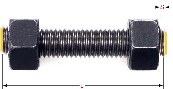
- The length of the Stud Bolt does not include the height of the chamfers (points).
- The length of the Stud Bolts includes one Spiral Wound Gasket with a 4.5mm thick sealing element, which is compressed to 3mm while tightening the Raised Face flange connection.
Tolerances
Tolerances on all dimensions shall be as shown in ASME B16.5 except for those shown below.
Pressure Tap Location
Tolerance on location of center of pressure tap hole from flange face shall be..
- ±0.5 mm (±0.02 in.) for flanges smaller than NPS 4
- ±0.8 mm (±0.03 in.) for flanges NPS 4 and larger
Bore Diameter
- Bore diameter tolerance (Welding Neck flanges only) is ±0.5% of nominal value.
Studs are measured parallel to the axis (L) from the first to the thread without the chamfers (points). S = free threads equals 1/3 time bolt dia
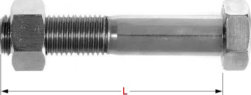
Hex bolts are measured from under the head to the end of the bolt