 |
Bolt Hole Orientation |
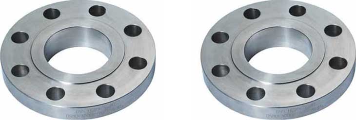
Bolt Holes for Flanges
Just as already circumscribed, ASME B16.5 is also de standard for the number and the diameter of the bolt holes in a flange. The numbers and diameters diverge per Pressure Class, but is for every typ of flange in a specific Pressure Class the same. The bolt holes are be similar divided over the diameter of the bolt circle, and the number is always an even number (4, 8, 12, 16 etc.).
Bolt Hole Orientation
During the prefab of a flange to for example a elbow, the position of the bolt holes are of particular importance. Maybe you have ever seen the following on a drawing..
All Flange Bolt Holes Straddle the Centerlines
That means..
For a vertical flange face (the flange face in the vertical and the line is horizontal) the bolt holes want to be orientated to straddle the vertical and horizontal centerlines.
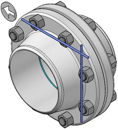
Correct vertical flange position...
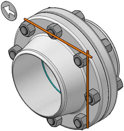
Incorrect vertical flange position...DO NOT !
For a horizontal flange face (the flange face is horizontal and the line is vertical above or vertical down) the bolt holes want to be orientated to straddle the Plant North centerlines. See below on this page, a image of a plant north situation.
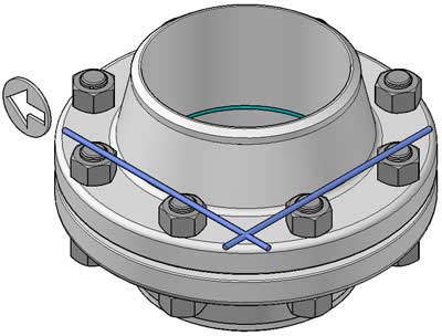
Correct horizontal flange position...
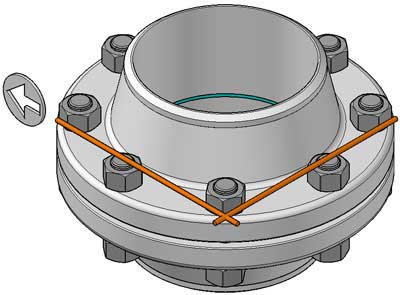
Incorrect horizontal flange position...DO NOT !
It is very important, that is not deviated from the standard bolt hole orientation. Only on explicit request, e.g. of the customer, may be a different orientation be applied. In 99 percent of all cases, where you will see a different orientation, you can assume that it is a mistake. This centerline rule for flanges, understood and followed by all responsible equipment manufacturers and piping fabricators.
Plant North
A plant north, is a horizontal reference point, and is derived from an official geographical reference point. A plant north is applied...see more about plant coordinates in the main Menu "Documents" Dimensioning from Reference Points.
1 = Official reference point
2 = South West angle of new plant
X = East West distance from new plant to reference point
Y = North South distance from new plant to reference point
Related Post(s)
Different types of flange faces are used as the contact surfaces to seat the sealing gasket material...