 |
Control valves |
Process plants consist of hundreds, or even thousands, of control loops all networked together to produce a product to be offered for sale. Each of these control loops is designed to keep some important process variable such as pressure, flow, level, temperature, etc. within a required operating range to ensure the quality of the end product. Each of these loops receives and internally creates disturbances that detrimentally affect the process variable, and interaction from other loops in the network provides disturbances that influence the process variable.
To reduce the effect of these load disturbances, sensors and transmitters collect information about the process variable and its relationship to some desired set point. A controller then processes this information and decides what must be done to get the process variable back to where it should be after a load disturbance occurs. When all the measuring, comparing, and calculating are done, some type of final control element must implement the strategy selected by the controller.
Principles of Operation
The most common final control element in the process control industries is the control valve. The control valve manipulates a flowing fluid, such as gas, steam, water, or chemical compounds, to compensate for the load disturbance and keep the regulated process variable as close as possible to the desired set point.
Control valves may be the most important, but sometimes the most neglected, part of a control loop. The reason is usually the instrument engineer's unfamiliarity with the many facets, terminologies, and areas of engineering disciplines such as fluid mechanics, metallurgy, noise control, and piping and vessel design that can be involved depending on the severity of service conditions.
Any control loop usually consists of a sensor of the process condition, a transmitter and a controller that compares the "process variable" received from the transmitter with the "set point," i.e., the desired process condition. The controller, in turn, sends a corrective signal to the "final control element," the last part of the loop and the "muscle" of the process control system. While the sensors of the process variables are the eyes, the controller the brain, then the final control element is the hands of the control loop. This makes it the most important, alas sometimes the least understood, part of an automatic control system. This comes about, in part, due to our strong attachment to electronic systems and computers causing some neglect in the proper understanding and proper use of the all important hardware.
What is a Control Valve?
Control valves automatically regulate pressure and/or flow rate, and are available for any pressure. If different plant systems operate up to, and at pressure/temperature combinations that require Class 300 valves, sometimes (where the design permits), all control valves chosen will be Class 300 for interchange-ability. However, if none of the systems exceeds the ratings for Class 150 valves, this is not necessary.
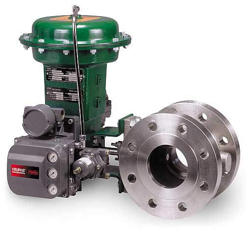
Globe valves are normally used for control, and their ends are usually flanged for ease of maintenance. Depending on their type of supply, the disk is moved by a hydraulic, pneumatic, electrical or mechanical actuator. The valve modulates flow through movement of a valve plug in relation to the port(s) located within the valve body. The valve plug is attached to a valve stem, which, in turn, is connected to the actuator.
Control Valve Arrangement
The image below shows how a control valve can be used to control rate of flow in a line. The "controller" receives the pressure signals, compares them with pressure drop for the desired flow and if the actual flow is different, adjusts the control valve to increase or decrease the flow.
Comparable arrangements can be devised to control any of numerous process variables. Temperature, pressure, level and flow rate are the most common controlled variables.
Image comes from www.steamline.com
Valve Types and typical Applications
| Valve type | Service and Function | |||
| IoS | TH | PR | DC | |
| Gate | YES | NO | NO | NO |
| Globe | YES | YES | NO | YES (note 1) |
| Check | (note 2) | NO | NO | NO |
| Stop check | YES | NO | NO | NO |
| Butterfly | YES | YES | NO | NO |
| Ball | YES | (note 3) | NO | YES (note 4) |
| Plug | YES | (note 3) | NO | YES (note 4) |
| Diaphragm | YES | NO | NO | NO |
| Safety Relief | NO | NO | YES | NO |
Legend..
- DC = Directional Change
- IoS = Isolation or Stop
- PR = Pressure Relief
- TH = Throttling
Notes..
- Only angle-globe valves can be used for a 90-degree change in direction of flow.
- Check valves (other than the stop-check valves) stop flow only in one (reverse) direction. Stopcheck valves can be and are used as stop, block, or isolation valves, in addition to being used as a check valve.
- Some designs of ball-and-plug valves (contact the valve manufacturer) are suitable for throttling service.
- Multiport ball-and-plug valves are used for changing the direction of flow and mixing flows.