Pressure Testing Codes |
There are many codes and standards relating to piping systems. Two codes of major importance for pressure and leak testing is the ASME Boiler and Pressure Vessel Code (BPVC) and the ASME B31.
The Several ASME B31 Standards
While these codes are applicable to many piping systems, other codes or standards may have to be met as required by the authorities, insurance companies, or the owner of the system. Examples might be AWWA standards for water transmission and distribution system piping.
Leak-Testing Methods
There are many different methods for pressure and leak testing in the field. Seven of these are..
- Hydrostatic testing, which uses water or another liquid under pressure
- Pneumatic or gaseous-fluid testing, which uses air or another gas under pressure
- A combination of pneumatic and hydrostatic testing, where low pressure air is first used to detect leaks
- Initial service testing, which involves a leakage inspection when the system is first put into operation
- Vacuum testing, which uses negative pressure to check for the existence of a leak
- Static head testing, which is normally done for drain piping with water left in a standpipe for a set period of time
- Halogen and helium leak detection
Hydrostatic Leak Testing
Hydrostatic testing is the preferred leak-testing method and perhaps the most often used. The most important reason for this is the relative safety of hydrostatic testing compared to pneumatic testing. Water is a much safer fluid test medium than air because it is nearly incompressible. Therefore, the amount of work required to compress water to a given pressure in a piping system is substantially less than the work required to compress air, or any other gas, to the same pressure. The work of compression is stored in the fluid as a potential energy, which could be released suddenly in the event of a failure during a pressure test.
A calculation of the potential energy of air compressed to a pressure of 1000 psig (6900 kPa) compared to the potential energy of the same final volume of water at 1000 psig (6900 kPa) shows a ratio of over 2500 to 1. Therefore, the potential damage to surrounding equipment and personnel resulting from a failure during a pressure test is far more serious when using a gaseous test medium. That is not to say that there is no danger at all in a hydrostatic leak test. There can be substantial danger in a hydrostatic test due to air trapped in the piping. Even if all air is vented from the piping before pressurizing, workers are well advised to conduct any high-pressure test with safety in mind.
Pneumatic Leak Testing
The fluid normally used for a pneumatic test is compressed air, or nitrogen if the source is bottled gas. Nitrogen should not be used in a closed area if the possibility exists that the escaping nitrogen could displace the air in the confined space. Persons have been known to become unconscious under such circumstances before realizing they were short of oxygen. Because of the greater danger of injury with a gaseous test medium, the pressure that may be used for visual examination for leaks is lower for some piping codes than is the case for a hydrostatic test. For example, for pneumatic tests, ASME B31.1 permits the pressure to be reduced to the lower of 100 psig (690 kPa) or the design pressure during the examination for leakage.
Combination Pneumatic and Hydrostatic Testing
A low air pressure, most often 25 psig, (175 kPa) is first used to see if there are major leaks. This low pressure reduces the danger of personal injury but still enables major leaks to be quickly located. Repairs, if needed, can then be done before the hydrostatic test. This method can be very effective in saving time, particularly if it takes a long time to fill a system with water only to find leaks on the first try. If leaks are found in a hydrostatic test, it will take longer to remove the water and dry the piping sufficiently to make repairs.
Hydrostatic-pneumatic leak testing is different from the two-step test in the preceding paragraph. In this case the pressure test is conducted with a combination of air and water. For example, a pressure vessel designed to contain a process liquid with a vapor phase or air above the liquid may have been designed to support the weight of liquid to a certain maximum-expected height of liquid. If the vessel was not designed to support the weight when completely filled with liquid, it would be possible to test this vessel only if it was partially filled with process fluid to a level duplicating the effect of the maximum-expected level.
Initial Service Leak Testing
This category of testing is limited by the codes to certain situations. For example, ASME B31.3 limits the use of this technique to category D fluid service. Category D fluid services are defined as nonhazardous to humans and must operate below 150 psi (1035 kPa) and at temperatures between -20 and 366°F (-29 and 185°C). ASME Code B31.1, section 137.7.1, does not allow initial service testing of boiler external piping. However, that same section of ASME B31.1 permits initial service testing of other piping systems if other types of leak testing are not practical. Initial service testing is also applicable to inspection of nuclear power plant components by Section XI of the ASME Boiler and Pressure Vessel Code. As indicated, this test is usually run when the system is first put into operation. The system is gradually raised to normal operating pressure as required in ASME B31.1 or design pressure as required in ASME B31.3. It is then maintained at that pressure while an examination for leaks is conducted.
Vacuum Leak Testing
Vacuum leak testing is an effective way to determine whether or not there is a leak anywhere in the system. This is normally done by drawing a vacuum on the system and trapping the vacuum within the system. A leak is indicated if the trapped vacuum rises toward atmospheric pressure. A manufacturer of components quite often uses this type of leak test as a production leak test. However, it is very difficult to determine the location or locations of a leak if one exists. Smoke generators have been used to determine the piping location where smoke is drawn into the piping. This is very difficult to utilize unless the leak is sufficiently great to draw all or most of the smoke into the pipe. If there is substantially more smoke generated than can be drawn into the pipe, the smoke that dissipates into the surrounding air can easily hide the leak location. Obviously, this method is not suitable for testing the piping at or above the operating pressure unless the piping is to be operated at a vacuum.
Static-Head Leak Testing
This test method is sometimes called a drop test because a drop in the water level in the open standpipe, added to the system to create the required pressure, is an indication of a leak. Once the system and standpipe is filled with water, the standpipe level is measured and noted. After a required hold period, the height is rechecked and any decrease in level and the hold period are recorded. Any leak location is determined by visual inspection.
Halogen and Helium Leak Testing
These test methods use a tracer gas to identify leakage location and leakage quantity. In the case of halogen leak detection, the system is charged with halogen gas. A halogen detector probe is used to sense leakage of the tracer gas from any exposed joint. The halogen leak detector, or sniffer, consists of a tubular probe which sucks a mixture of leaking halogen gas and air into an instrument sensitive to small amounts of halogen gas.
This instrument employs a diode to sense the presence of halogen gas. The leaking halogen gas is passed over a heated platinum element (the anode). The heated element ionizes the halogen gas. The ions flow to a collector plate (the cathode). Current proportional to ion formation rate, and thus to leakage flow rate, is indicated by a meter. The halogen detector probe is calibrated using an orifice that passes a known leakage flow. The detector probe is passed over the orifice at the same rate that will be used to examine the system for leakage. The preferred tracer gas is refrigerant 12, but refrigerants 11, 21, 22, 114, or methylene chloride may be used. Halogens should not be used with austenitic stainless steels.
Helium leak testing may also be done in the sniffer mode, as explained above for halogens. However, in addition, helium leak testing may be performed using two other methods that are more sensitive in detecting leakage. These are the tracer mode and the hood or closed system mode. In the tracer mode a vacuum is drawn on the system, and helium is sprayed onto the outside of joints to be inspected for leakage. The system vacuum draws helium through any leaking joint and delivers it to a helium mass spectrometer. In the hood mode, the system to be tested is surrounded by concentrated helium.
The hood mode of helium leak testing is the most sensitive method for detecting leaks and the only method accepted by ASME Code Section V as quantitative. Manufacturers of components requiring a hermetic seal will use the hood method of helium leak detection as a production leak test. In these cases, the component may be surrounded by helium in a chamber.A connection to the component is made to a helium leak detector, which attempts to draw the internals of the component to a vacuum close to absolute zero.
Any leakage of helium from the surrounding chamber into the component will de drawn into the helium leak detector by the vacuum it is producing. The helium leak detector contains a mass spectrometer configured to sense the presence of helium molecules. This closed-system testing method is capable of sensing leaks as small as 1X10⁻¹⁰cc/sec (6.1X10⁻¹² cubic in/sec), standard atmospheric air equivalent. The closed-system method is not appropriate to measuring a large leak that would flood the detector and render it useless for further measurement until every helium molecule could be withdrawn from the detector.
The closed-system method is not appropriate to a piping system in the field because of the large volumes. Also it does not show the location of the leak or leaks. Finally, the sensitivity of leak detection, using the closed system, is many orders of magnitude greater than normally required. The helium sniffer is the least sensitive method and is subject to false indications if helium from a large leak at one location in the system diffuses to other locations.
A large leak can also flood the detector, temporarily rendering it useless until all the helium is removed from the mass spectrometer. The helium pressure used in all these methods is normally one or two atmospheres, which is sufficient to detect the presence of very small leaks. The low pressure also serves to reduce the amount of helium required for the test. Helium leak testing is rarely, if ever, used to demonstrate that the system can safely withstand the design pressure rating.
Helium leak detectors will not be successful in finding leaks unless the component or piping system is completely dry. Liquid contained in a small leakage path, due to capillary action, may seal the leak because of the low pressure of the helium and the surface tension of the liquid. Therefore great care is required to use this approach under completely dry conditions. Otherwise this system may be even less sensitive in detecting a leak than a high-pressure hydrostatic test. Furthermore, the helium leak detector is easily contaminated by oils and other compounds and rendered inaccurate. Field conditions are normally not free of the possibility for contamination of the leak detector.
Test Pressures
The selected test method and fluid test medium, together with the applicable code, will also establish the rules to be followed in calculating the required test pressure. In most cases a pressure greater than the design pressure rating is applied for a short duration, say at least 10 minutes. The magnitude of this initial test pressure is often at least 1.5 times the design pressure rating for a hydrostatic test. However, it may be different, depending upon which code is applicable and whether the test is hydrostatic or pneumatic.
Furthermore, the test pressure must never exceed a pressure that would cause yielding, or the maximum allowable test pressure of some component exposed to the test. In the case of ASME B31, section 137.1.4, and the Boiler and Pressure Vessel Codes, the maximum test pressure must not exceed 90 percent of yield for any component exposed to the test. The test pressure is needed to demonstrate that the system can safely withstand the rated pressure. Following this period of greater than design pressure, it is often permissible to reduce the pressure to a lower value for examination of leaks. The examination pressure is maintained for the length of time necessary to conduct a thorough
| Code | Test type |
| ASME B31.1 | Hydrostatic (1) |
| ASME B31.1 | Pneumatic |
| ASME B31.1 | Initial service |
| ASME B31.3 | Hydrostatic |
| ASME B31.3 | Pneumatic |
| ASME B31.3 | Initial service (3) |
| ASME I | Hydrostatic |
| ASME III Division 1 Subsection NB |
Hydrostatic |
| ASME III Division 1 Subsection NB |
Pneumatic |
| ASME III Division 1 Subsection NC |
Hydrostatic |
| ASME III Division 1 Subsection NC |
Pneumatic |
| ASME III Division 1 Subsection ND |
Hydrostatic |
| ASME III Division 1 Subsection ND |
Pneumatic |
| Code | Test pressure minimum |
| ASME B31.1 | 1.5 times design |
| ASME B31.1 | 1.2 times design |
| ASME B31.1 | Normal operating pressure |
| ASME B31.3 | 1,5 times design (2) |
| ASME B31.3 | 1.1 times design |
| ASME B31.3 | Design pressure |
| ASME I | 1.5 times max allowable working pressure (4) |
| ASME III Division 1 Subsection NB |
1.25 times system design pressure (5) |
| ASME III Division 1 Subsection NB |
1.25 times system design pressure (6) |
| ASME III Division 1 Subsection NC |
1.5 times system design pressure |
| ASME III Division 1 Subsection NC |
1.25 times system design pressure |
| ASME III Division 1 Subsection ND |
1.5 times system design pressure for completed components, 1,25 times system design pressure for piping systems |
| ASME III Division 1 Subsection ND |
1.25 times system design pressure |
| Code | Test pressure maximum |
| ASME B31.1 | Max allowable test pressure any component or 90 percent of yield |
| ASME B31.1 | 1.5 times design or max allowable test pressure any componenet |
| ASME B31.1 | Normal operating pressure |
| ASME B31.3 | Not to exceed yield stress |
| ASME B31.3 | 1.1 times design plus the lesser of 50 psi or 10 percent of test pressure |
| ASME B31.3 | Design pressure |
| ASME I | Not to exceed 90 percent yield stress |
| ASME III Division 1 Subsection NB |
Not to exceed stress limits of design section NB-3226 or maximum test pressure of any system componenet (5) |
| ASME III Division 1 Subsection NB |
Not to exceed stress limits of design section NB-3226 or maximum test pressure of any system componenet |
| ASME III Division 1 Subsection NC |
If minimum test pressure exceeded by 6 percent establish limit by the lower of analysis of all test loadings or maximum test pressure of any componenet |
| ASME III Division 1 Subsection NC |
If minimum test pressure exceeded by 6 percent establish limit by the lower of analysis of all test loadings or maximum test pressure of any componenet |
| ASME III Division 1 Subsection ND |
If minimum test pressure exceeded by 6 percent establish limit by the lower of analysis of all test loadings or maximum test pressure of any componenet |
| ASME III Division 1 Subsection ND |
If minimum test pressure exceeded by 6 percent establish limit by the lower of analysis of all test loadings or maximum test pressure of any componenet |
| Code | Test pressure hold time |
| ASME B31.1 | 10 minutes |
| ASME B31.1 | 10 minutes |
| ASME B31.1 | 10 minutes or time to complete leak examination |
| ASME B31.3 | Time to complete leak examination but at least 10 minutes |
| ASME B31.3 | 10 minutes |
| ASME B31.3 | Time to complete leak examination |
| ASME I | Not specified, typically 1 hr |
| ASME III Division 1 Subsection NB |
10 minutes |
| ASME III Division 1 Subsection NB |
10 minutes |
| ASME III Division 1 Subsection NC |
10 or 15 minutes per inch of design minimum wall thickness for pumps and Valves |
| ASME III Division 1 Subsection NC |
10 minutes |
| ASME III Division 1 Subsection ND |
10 minutes |
| ASME III Division 1 Subsection ND |
10 minutes |
| Code | Examination pressure |
| ASME B31.1 | Design pressure |
| ASME B31.1 | Lower of 100 psig or design pressure |
| ASME B31.1 | Normal operating pressure |
| ASME B31.3 | 1.5 times design |
| ASME B31.3 | Design pressure |
| ASME B31.3 | Design pressure |
| ASME I | Max allowable working pressure (4) |
| ASME III Division 1 Subsection NB |
Greater of design pressure or 0,75 times test pressure |
| ASME III Division 1 Subsection NB |
Greater of design pressure or 0,75 times test pressure |
| ASME III Division 1 Subsection NC |
Greater of design pressure or 0,75 times test pressure |
| ASME III Division 1 Subsection NC |
Greater of design pressure or 0,75 times test pressure |
| ASME III Division 1 Subsection ND |
Greater of design pressure or 0,75 times test pressure |
| ASME III Division 1 Subsection ND |
Greater of design pressure or 0,75 times test pressure |
Notes..
| 1. | Boiler external piping must be hydrostatic tested in accordance with PG-99 of ASME Code Section I. |
| 2. | ASME B31.3 hydrostatic pressure must be raised above 1.5 times design pressure in proportion to yield strength at test temperature divided by strength at design temperature but not to exceed yield strength at test temperature. Where a vessel is involved whose design pressure is less than the piping and where vessel cannot be isolated, the piping and vessel can be tested together at vessel test pressure provided vessel test pressure is not less than 77 percent of piping test pressure. |
| 3. | ASME B31.3 initial service testing permitted only for piping in category D service. |
| 4. | ASME Code Section I hydrostatic test pressure at temperature of at least 70°F (21°C) and examination pressure at temperature less than 120°F (49°C). For a forced-flow steam generator with pressure parts designed for different pressure levels, the test pressure should be at least 1.5 times the maximum allowable working pressure at the superheater outlet but not less than 1.25 times the maximum allowable working pressure of any part of the boiler. |
| 5. | ASME Code Section III, Division 1, subsection NB, test pressure limits defined in section NB3226; also components containing brazed joints and Valves to be tested at 1.5 times system-design pressure prior to installation. |
| 6. | ASME Code Section III, Division 1, subsection NB, pneumatic test pressure for components partially filled with water shall not be less than 1.25 times system-design pressure. |
Pressure Equipment Failure
Pressure vessel and piping systems are widely used throughout industry and contain a very large concentration of energy. Despite the fact that their design and installation comply with federal, state and local regulations and recognized industrial standards, there continue to be serious pressure equipment failures.
There are many reasons for pressure equipment failure.. degradiation and thinning of materials during peration, aging, hidden flaws during fabrication, etc.. Fortunately, periodic testing and internal and external inspections significantly improve the safety of a pressure vessel or piping system. A good testing and inspection program is based on development of procedures for specific industries or types of vessels.
A number of accidents has served to focus attention on the hazards and risks associated with storage, handling, and transfer of fluids under pressure. When pressure vessels do fail, it is typically the result of shell failure resulting from corrosion and erosion (more than 50 percent shell failures).
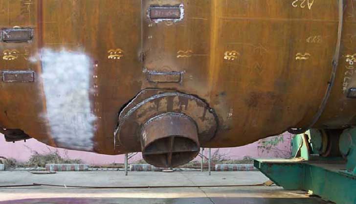 New constructed vessel ripped open during a hydrotest
All pressure vessels have their own peculiar hazards, including great stored potential force, points of wear and corrosion, and possible failure of overpressure and temperature control safety devices.
Government and industry have responded to the need for improved pressure systems testing by producing standards and regulations specifying general pressure safety requirements (ASME Boiler and Pressure Vessel Code, DOE Pressure Safety Guidelines and others).
These regulations outline requirements for implementation of a pressure testing safety program. It is critical that design and operating personnel use these standards as benchmark criteria for writing and implementing a pressure testing safety program.
Pressure Testing Program
A good pressure testing safety program should detect fabrication defects and deterioration from aging, cracking, corrosion and other factors before they cause vessel failure and to determine (1) if the vessel can continue to be operated at the same pressure, (2) what measures of control and repair may be needed so that the pressure system can be operated at the original pressure, and (3) whether pressure must be reduced in order to operate the system safely.
All companies, working with pressurized equipment, almost all have expanded engineering guidelines for testing of pressure vessels and piping systems. These guidelines are prepared in accordance with the pressure safety standards of OSHA, DOT, ASME, local, state, and other federal codes and standards.
The documentation includes definition of the responsibilities of engineering, management, and safety personnel; the general requirements for equipment and materials; procedures for hydrostatic and pneumatic testing to verify the integrity of a system and its components; and guidelines for a pressure testing plan, emergency procedures, documentation, and hazard control measures. These measures include pressure release control, protection against the effects of noise exposure, environmental and personal monitoring, and protection from the presence of toxic or flammable gases and high pressures.
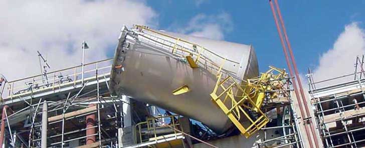 Launch of a newly manufactured tank during a pneumatic pressure test with air
Pressure Testing Definitions
- Alteration - An alteration is a physical change in any component that has design implications which affect the pressure containing capability of a pressure vessel beyond the scope of the items described in existing data reports.
- Corrosion Allowance - The extra thickness of material added by design to allow for material loss from corrosive or erosive attack.
- Corrosive Service - Any pressure system service that, because of chemical or other interaction with the container's materials of construction, contents, or external environment, causes the pressure container to crack, to become embrittled, to lose more than 0.01 in. of thickness per year of operation, or to eteriorate in any way.
- Design Pressure - the pressure used in the design of a pressure component together with the coincident design metal temperature, for the purpose of determining the minimum permissible thickness or physical characteristics of the pressure boundary. Design pressure for vessels is shown on the fabrication drawings and for piping, the maximum operating pressure is indicated on the line list. The design pressure for piping is the larger of 110% of the maximum operating pressure or 25 psi over the maximum operating pressure.
- Engineering Safety Note (ESN) - A management-approved document describing the anticipated hazards sociated with equipment and the design parameters that will be used.
- High Pressure - Gas Pressure greater than 20 MPa gauge (3000 psig) and liquid pressure greater than 35 MPa gauge (5000).
- Intermediate Pressure - Gas Pressure from 1 to 20 MPa gauge (150 to 3000 psig) and liquid pressure from 10 to 35 MPa gauge (1500 to 5000 psig).
- Leak Test - A pressure or vacuum test to determine the existence, rate, and/or location of a leak.
- Low Pressure-Gas Pressure less than 1 MPa gauge (150 psig) or liquid pressure less than 10 MPa (1500 psig).
- Manned-area operation - A pressure operation, that may be conducted (within specified limits) with personnel present.
- Maximum Allowable Working Pressure (MAWP) - maximum pressure permissible at the top of a vessel in its normal operating position at the operating temperature specified for the pressure. It is the least of the values found for maximum allowable working pressure for any of the essential parts of the vessel by the principles established in ASME Section VIII. The MAWP is shown on the vessel nameplate. The MAWP may be taken same as the design pressure, but for the most part the MAWP is based on the fabricated thickness minus the corrosion allowance. MAWP applies to pressure vessels only.
- Maximum Design Temperature - is the maximum temperature used in the design and shall not be less than the maximum operating temperature.
- Maximum Operating Pressure (MOP) - The highest pressure expected during operation. This is usually 10-20% below the MAWP.
- Minimum Allowable Metal Temperature (MAMT) - The minimum temperature for an existing vessel to sustain the testing or operating conditions with a low risk of brittle fracture. The MAMT is determined by an evaluation for pressure vessels built prior to 1987. This term is used in API RP 579 for the brittle fracture evaluation of existing equipment. It may be a single temperature, or an envelope of acceptable operating temperatures as a function of pressure.
- Minimum Design Metal Temperature (MDMT) - The minimum metal temperature used in the design of a pressure vessel. The MDMT is an ASME Code term and normally shown on the vessel nameplate or U-1 Form for vessels designed per ASME Section VIII, Division 1, 1987 edition or later.
- Mpa - Absolute pressure in SI units. 1 atmosphere (14.7 psig) is equal to 0.1 MPa.
- Operational Safety Procedure (OSP) - The Document used to describe the controls necessary to ensure that the risks associated with a potentially hazardous research project or unique activity are at an acceptable level.
- Pressure Equipment - Any equipment, e.g., vessels, manifolds, piping, or other components, that operates above or below (in the case of vacuum equipment) atmospheric pressure.
- Pressure Vessel - A relatively high-volume pressure component (such as a spherical or cylindrical container) with a cross section larger than the associated piping.
- Proof Test - A test in which equipment prototypes are pressurized to determine the actual yield or failure (burst) pressure (used to calculate the MAWP).
- Remote Operation - A pressure operation, that may not be conducted with personnel present. The equipment must be installed in test cells, behind certified barricades, or be operated from a safe location.
- Safety Factor (SF) - The ratio of the ultimate (i.e., burst or failure) pressure (measured or calculated) to the MAWP. A Safety Factor related to something other than the failure pressure should be identified with an appropriate subscript.
Codes, Standards and References
American Society of Mechanical Engineers (ASME)
- Boiler and Pressure Vessel Code.. Section VIII Pressure Vessels
- ASME B31.3 Chemical Plant and Petroleum Refinery Piping
- ASME B16.5 Pipe Flanges and Flanged Fittings
American Society for Testing and Materials (ASTM)
- ASTM E 1003 Standard Test Method for Hydrostatic Leak Testing
American Petroleum Institute (API)
- RP 1110 Pressure Testing of Steel Pipelines for the Transportation of Gas, Petroleum Gas, Hazardous Liquids...
- API 510 Maintenance, Inspection, Rating, Repair, and Alteration
- API 560 Fired Heaters for General Refinery Services
- API 570 Inspection, Repair, Alteration, and Rerating of In-Service Piping Systems
- API 579 Draft of API Recommended Practice for Fitness-For-Service
Interesting articles about pressure testing failure
Pressure Vessel Failure during Pneumatic Test
Pressure Vessel Failure during Hydro Test
Pressure Vessel Failure during Air Test
Remark(s) of the Author...
Pressure Testing ASME B31.3
Piping systems are typically designed and built per an applicable code. Certainly the use of ASME B31.3 could be applicable to ships carrying oil, but you should really be following the code that the piping system was designed to. Since I'm familiar with B31.3 and not the European (or other country's) equivalent, I'll base this response on B31.3.
ASME B31.3 requires "leak testing" of the piping system. This is not a structural test, it is only a test to determine if there are points within the system that are leaking.* On the other hand, there are codes which may require a structural test such as is done by the boiler and pressure vessel code. In that case, the hydrostatic test is performed to verify that the vessel and attached piping is structurally sound, not just leak tight.
ASME B31.3, Para. 345.1 states..
Prior to initial operation, and after completion of the applicable examinations required by para. 341, each piping system shall be tested to ensure tightness. The test shall be a hydrostatic leak test in accordance with para. 345.4 except as provided herein.
Where the owner considers a hydrostatic leak test impractical, either a pneumatic test in accordance with para. 345.5 or a combined hydrostatic-pneumatic test in accordance with para. 345.6 may be substituted, recognizing the hazard of energy stored in compressed gas.
So per the code, a leak test using air may be performed if the system owner considers the hydrostatic test to be impractical.
It's important to understand that the pressure at which the test is performed is a function of the design pressure. Design pressure is a function of the allowable stress limits on the piping which is also a function of operating temperature.
- For a hydrostatic test, para. 345.4.2 requires a pressure of not less than 1.5 times the design pressure.
- For a pneumatic test, para. 345.5.4 requires a pressure of not less than 110% of design pressure.
Next step is for an engineer (preferably the piping system designer or stress analyst) to create pressure test procedures. These pressure test procedures look at the possibility of low temperature brittle failure, which may be a concern at the temperatures you're referring to. The pressure test procedures are actually a set of procedures (typically) which include such things as method of pressurizing system, valve positions, removal of relief devices, isolation of portions of the piping system, etc.
Regarding the low temperature, para. 345.4.1 states.. "The fluid shall be water unless there is a possibility of damage due to freezing or to adverse effects of water on the piping or the process (see para. F345.4.1). In that case, another suitable non-toxic liquid may be used." So glycol/water is allowed.
If the test is to be done pneumatically, test pressure should be raised to 25 psi at which time a preliminary check shall be made, including examination of all joints. The use of a low temperature bubble fluid is highly advisable.
So to conclude..
- If the specification you've been given is to perform a hydro test at 16 bar, then that should be 1.5 times the design pressure of 10.67 bar. Per B31.3, a pneumatic test should therefore be performed not at 16 bar, but at 1.1 times the design pressure or 11.7 bar. Run the pneumatic pressure only as high as 11.7 bar.
- The possibility of brittle failure should be reviewed by the appropriate engineer. In the case of temperature below 0 C, the material used should be examined to verify it is not below the minimum useable temperature for that steel.
- A cognizant engineer needs to produce a set of pressure test procedures. Those procedures need to indicate what sections of pipe are being tested, what positions valves should be placed in, what relief devices need to be removed (or installed), etc.
- The pneumatic test needs to start at 25 psig and a preliminary examination for leaks performed prior to increasing pressure.
- Most important, the cognizant engineer must also examine the piping design specification for all requirements pertaining to leak or pressure testing.
Although B31.3 describes this as a "leak test", when performed hydrostatically at 1.5 times design, it is in affect, a structural test.