Oil and Gas extraction
Nodding Donkey
A pumpjack (also known as nodding donkey) is the popular name for the aboveground part of a pump that pumping oil from the ground.
With the use of a drilling rig, a well is drilled to the oil field, and a pipe is connected to the source to a submersible pump. This pump is located deep under the ground, and is driven by an electric motor placed above ground.
The Nodding Donkey is responsible for the mechanical transmission to the piston in the underground pump. It is used to mechanically lift liquid out of the well if there is not enough bottom hole pressure for the liquid to flow all the way to the surface.
The arrangement is commonly used for onshore wells producing relatively little oil. Pumpjacks are common in many oil-rich areas, dotting the countryside and occasionally serving as local landmarks.
Depending on the size of the pump, it generally produces 5 to 40 litres of liquid at each stroke. Often this is an emulsion of crude oil and water. The size of the pump is also determined by the depth and weight of the oil to be removed, with deeper extraction requiring more power to move the heavier lengths of sucker rods.
A pumpjack converts the rotary mechanism of the motor to a vertical reciprocating motion to drive the pump shaft, and is exhibited in the characteristic nodding motion. The engineering term for this type of mechanism is a walking beam. It was often employed in stationary and marine steam engine designs in the 18th and 19th centuries.
Above ground
The body of the pumpjack is called a walking beam, and it acts as a giant lever. At the tail end of the
pumpjack is a crank and a counterweight, which work together to move the walking beam up and down. As
the walking beam moves the "head" bobs up and down as well. A long metal rod called a "bridle" extends
downward from the head and penetrates deep into the ground, reaching the oil well. As the pumpjack's
head bobs up and down, the rod goes up and down as well.
Bellow ground
The main underground mechanism in a pumpjack contains two Valves; a standing Valve at the bottom of the
rod with a traveling Valve right above it. The area between the two Valves is called the pump barrel.
When the rod moves upward, the pressure inside the pump barrel decreases, which opens the standing Valve
and closes the traveling Valve. The traveling Valve therefore moves upwards and the oil below the rod
flows into the pump barrel.
As the rod descends, the pressure inside the pump barrel increases, which closes the standing Valve and opens the traveling Valve. Therefore, the oil in the pump barrel flows to the area above the traveling Valve. As the rod ascends once again and the traveling rod moves upwards, the oil above it flows up the rod as well. In this manner, oil is continuously pumped from the ground.
Oil and Gas Well Drilling
Today, almost all oil and gas wells are drilled using rotary drilling. In rotary drilling, a length of steel pipe (the drillpipe) with a drill bit on the end is rotated to cut a hole called the well bore. As the well goes deeper, additional sections of drillpipe are added to the top of the rotating drill string. Rotary drilling uses a steel tower to support the drillpipe. If the tower is part of a tractor-trailer and is jacked up as a unit, it is called a mast. If it is constructed on site, it is called a derrick. Both towers are constructed of structural steel and sit on a flat steel surface called the drill or derrick floor; this is where most of the drilling activity occurs. Four major systems comprise an operational rotary drilling rig.. the power supply, the hoisting system, the rotating system, and the circulating system.
An operational rig requires a dependable power supply in order for the other rig systems to operate. Power to these systems may be supplied through one or more diesel engines used alone or in conjunction with an electrical power supply.
The hoisting system raises, lowers, and suspends equipment in the well and typically consists of a drilling or hoisting line composed of wound steel cable spooled over a revolving reel. The cable passes through a number of pulleys, including one suspended from the top of the derrick or mast. The hoisting system is used to move drillpipe into or out of the well.
The rotating system includes the turning drillpipe, the drill bit, and related equipment. It cuts the well bore, which may have an initial diameter of 20 in. (51 cm) or more but is usually less. The drill bit is located at the bottom end of the first drillpipe within the rotating system. The drillpipe is rotated by a rotary table located on the derrick floor. The drillpipe consists of heattreated alloy steel and may range in length from 18 to 45 ft (5 to 14 m); drillpipe length is typically uniform at each individual drilling rig. Before the drillpipe is fully inserted into the well bore, another section of drillpipe is added.
During drilling, the circulating system pumps drilling mud or fluids into the well bore to cool the drill bit, remove rock chips, and control subsurface fluids. Typically, mud is circulated down through the hollow drillpipe. The mud exits the pipe through holes or nozzles in the drill bit, and returns to the surface through the space between the drillpipe and the well bore wall.
Drilling Muds
Drilling muds (also termed fluids) are used during the drilling process to transport rock chips (cuttings) from the bottom of the well up and out of the well bore, where the cuttings are screened and removed, and the separated mud is reused. Drilling muds also act to cool the drill bit, to stabilize the well walls during drilling, and to control formation fluids that may flow into the well.
The most common drilling mud is a liquid-based mud typically composed of a base fluid (such as water, diesel oil, mineral oil, or a synthetic compound), with optional additives such as weighting agents (most commonly barium sulfate), bentonite clay (to help remove cuttings and to form a filler cake on the well bore walls), and lignosulfates and lignites (to keep the mud in a fluid state) (DOE 2005c).
Water-based muds and cuttings can be readily disposed of at most onshore locations, and in many U.S. offshore waters offshore disposal occurs as long as applicable regulatory effluent guidelines are met. In contrast, oil-based muds from onshore wells have more stringent land disposal requirements and are prohibited from discharge from offshore well platforms.
Synthetic-based muds use nonaqueous chemicals (other than oils) as their base fluid, such as internal olefins, esters, linear alpha-olefins, or linear paraffins. While these fluids have a lower toxicity, undergo more rapid biodegradiation, and have a lower bioaccumulation potential than oil-based fluids, they are also prohibited from offshore discharge.
Blowout Preventer (BOB)
All drilling sites include a blowout preventer. The blowout preventer, which is routinely used in onshore and offshore drilling, is intended to prevent oil, gas, and / or other subsurface liquids (i.e., salt water) from leaving the well and escaping into the atmosphere, onto the ground, into adjacent water bodies, or overlying waters.
At the bottom of a well, there are two fluid pressures. Pressure on fluids in the formation tries to force the fluids to flow from the formation into the well. Pressure exerted by the weight of the drilling mud filling the well tries to force the drilling mud into the surrounding rocks. Under normal operations, the effective weight of the drilling mud is adjusted to exert a slightly greater pressure on the bottom of the well than the effective pressure on the fluid in the rocks, causing the mud to enter the rock and cover the sides of the well and thus stabilize the well.
If the pressure on the fluid in the rocks is greater than the pressure of the drilling mud, water, gas, or oil will flow out of the rock into the well. In extreme cases, a blowout occurs where the fluids flow uncontrolled into the well and on occasion violently to the surface. A blowout preventer is a device that is used to close off a well if there is a loss of control of the fluids in the formation.
There are a variety of types of blowout preventers.Some close over the top of the well bore, some are designed to seal around the tubular components in the well (such as the drillpipe, casing, or tubing), and some have hardened steel shearing surfaces that actually cut through the drillpipe to seal off the opening.
Critical Components in a Complex System
Reference(s) .. New York Times (By Mika Gröndahl, Haeyoun Park, Graham Roberts And Archie Tse) Article Excerpt (January 27, 2011)
After the explosion of the Deepwater Horizon oil rig, investigators focused on the failure of a component on the well's blowout preventer that is supposed to close off a well spewing out of control. The device, called a blind shear ram, is the only part of the blowout preventer that can completely seal the well. Minutes after the explosion, at least one rig worker hit an emergency button, which is supposed to trigger the blind shear ram within about 30 seconds, and then disconnect the rig from the well. But that night, the blind shear ram never fully deployed.
Inside the Blowout Preventer
What Should Happen in an Emergency
- In a blowout, a rig worker presses an emergency button. A signal is sent from the rig down an electrical line to one of the control pods.
- The control pod directs hydraulic fluid from the rig and from a bank of pressurized canisters, called accumulators.
- Through a Valve, called a shuttle Valve, and into the blind shear ram. Some blowout preventers have a separate emergency system with its own shuttle Valve.
- The blind shear ram cuts through the drill pipe and seals the well, preventing oil from gushing out.
Inside the Blind Shear Ram
Of all the components on the blowout preventer, only the blind shear ram was designed to shut down the well in a blowout like the one that took place on the Deepwater Horizon oil rig on 20 April 2010. It is the only device that is supposed to cut through the thick drill pipe and seal off the hole.
Unlike many other parts of the Deepwater Horizon's blowout preventer, the blind shear ram has no backup. The breakdown of any part of the ram can lead to disaster. One of the most critical components of the blind shear ram is the shuttle Valve, the only point for the hydraulic fluid to enter the ram.
A risk analysis commissioned by the manufacturer of the blowout preventer identified this Valve as one of the weakest links. As the fluid flows through the system, it has two possible pathways until it reaches the Valve. So if the Valve fails, the well will not be sealed.
How it works
- Fluid enters the shuttle Valve from one of two inlet ports and pushes a metal "shuttle" to one side and flows down the stem of the T-shaped Valve.
- The fluid flows behind pistons, which drive the ram to shear the drill pipe.
- Wedge locks slide in to prevent the pistons from moving back.
- Rubber seals on the ram close off the well. Oil pushing up from the well adds pressure below and behind the ram, helping to keep the ram closed.
How the Ram Cuts the Drill Pipe
Reference(s) .. BP, Benton Baugh, Radoil, a deepwater engineering firm; Cameron; "Marine Riser Systems and Subsea Blowout Preventers," Petroleum Extension Service, The University of Texas at Austin and International Association of Drilling Contractors, West Engineering Services
Offshore Drilling
A major difference between onshore and offshore drilling is the nature of the drilling platform. In addition, in offshore drilling the drillpipe must pass through the water column before entering the lake or seafloor. Offshore wells have been drilled in waters as deep as 10,000 ft (305 m). The following text provides an overview of drilling in offshore environments.
Drilling template
Offshore drilling requires the construction of an artificial drilling platform, the form of which depends
on the characteristics of the well to be drilled. Offshore drilling also involves the use of a drilling
template that helps to connect the underwater drilling site to the drilling platform located at the water's
surface. This template typically consists of an open steel box with multiple holes, depending on the
number of wells to be drilled. The template is installed in the floor of the water body by first excavating
a shallow hole and then cementing the template into the hole. The template provides a stable guide for
accurate drilling while allowing for movement in the overhead platform due to wave and wind action.
Drilling platforms
There are two types of basic offshore drilling platforms, the movable drilling rig and the permanent
drilling rig. The former is typically used for exploration purposes, while the latter is used for the
extraction and production of oil and/or gas.
A variety of movable rigs are used for offshore drilling. Drilling barges are used in shallow (<20 ft [<6 m] water depth), quiet waters such as lakes, wetlands, and large rivers. As implied by the name, drilling barges consist of a floating barge that must be towed from location to location, with the working platform floating on the water surface. In very shallow waters, these may be sunk to rest on the bottom. They are not suitable for locations with strong currents or winds and strong wave action. Like barges, jack-up rigs are also towed, but once on location three or four legs are extended to the lake bottom while the working platform is raised above the water surface; thus, they are much less affected by wind and water current than drilling barges. Submersible rigs are also employed in shallow waters and, like jack-up rigs, are in contact with the lake bottom. These rigs include platforms with two hulls positioned above one another, with the lower hull acting like a submarine. When being towed to a new location, the lower hull is filled with air and serves to float the entire platform. Once on location, the lower hull is filled with water, and the rig sinks until the legs make contact with the lake bottom. As with the previous movable rigs, use of this type is limited to shallow water areas. Because of their size and relative ease of transport to drill sites, shallow water rigs would be the most likely type of rig that could be employed in the Great Lakes.
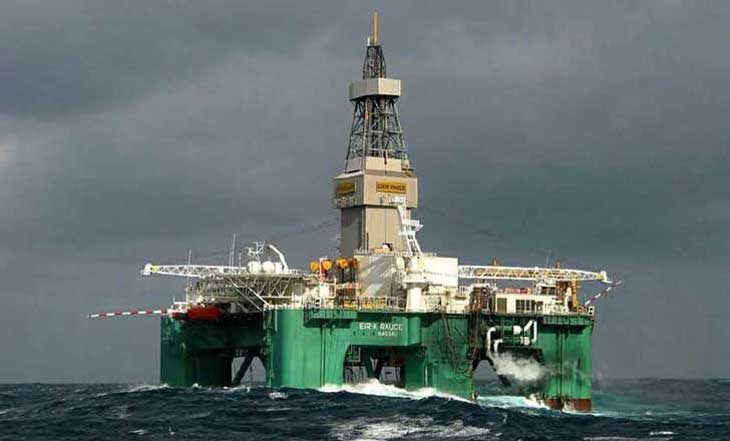
Eirik Raude rig is designed to carry out drilling operations in water depths down to 10 000 feet. Eirik Raude remains stable in harsh weather conditions owing to its superior motion characteristics and advanced dynamic positioning systems
The most common movable offshore drilling rig is the semi-submersible rig. It functions in a similar manner to the submersible rig, with a lower hull that can be filled or emptied of water. However, this type of rig does not contact the lake floor but floats partially submerged and is held in place through a number of anchors. This type of rig provides a stable and safe working platform in deeper and more turbulent offshore environments, and when high reservoir pressures are expected. The final type of movable drilling rig is the drillship. These are ships designed to carry drilling platforms great distances offshore and in very deep waters. A drilling platform and derrick are located in the middle of a large, open area of the ship, and the drill is extended through the ship to the drilling template.
When exploratory drilling locates commercially viable oil or gas deposits, a more permanent drilling platform is required to support well completion and oil and/or gas extraction. A variety of such production platforms are used for offshore drilling. Fixed platforms are typically used in areas with water depths less than 1,500 ft (457 m) and would be the most likely type of production platform that would be used in the Great Lakes. These platforms contact the bottom using concrete or steel legs and are either directly attached to, or simply rest on, the bottom. A variety of other production platforms are available for deeper water conditions and would probably not be applicable for use in the Great Lakes.
Drilling techniques
Conventional wells are drilled vertically from the surface straight down to the pay zone. This is the traditional and still common type of drilling.
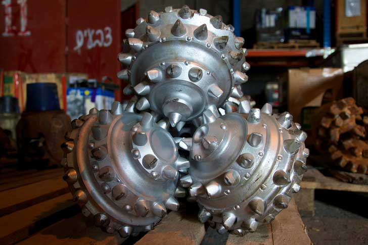
Typical Drilling Bit
Horizontal Drilling using technologies such as bottom driven bits, drillers are able to execute a sharp turn and drill horizontally along a thin pay zone. In a related procedure, developed in this area, two horizontal well bores are drilled one above the other, about 3 meters apart. One application for this is SAGD (Steam Assisted Gravity Drainage) where steam is injected into the higher of these horizontal holes and the heat precipitates oil down into the lower hole, increasing production of heavy oil. Drilling these holes requires an experienced crew, precision techniques and advanced technology.
Slant Drilling at an angle from perpendicular (commonly 30° to 45°). This approach minimizes surface environmental disturbance. For example, oil reserves under a lake can be tapped by a slant hole drilled from on shore. More commonly in this area; four, six, even eight slant wells are drilled from one "pad" (i.e. well lease site). This allows the oil reserves under a large land area to be tapped by only one well site. Thus, production of valuable oil reserves is effectively harmonized with conserving the environment.
(left to right) Conventional, Slant, Horizontal
Image comes from http://www.lloydminsterheavyoil.com/
Directional Drilling has advanced from slant and horizontal drilling to drilling that can change direction and depth several times in one well bore. A schematic of these drill bores (often several from the same drill pad, resembles the roots of a plant. This type of drilling is uniquely suited to pay zones in the Lloydminster area which are often distributed like prairie sloughs across the underground landscape. Directional drilling is also being applied in other parts of the world now such as Venezuela and where there is a special need to limit environmental impact on the surface.
Oil and Gas - Offshore Drilling by Woodside

Well Completion
Once a well has been drilled and verified to be commercially viable, it must be completed to allow for the flow of oil or gas. The completion process involves the strengthening of the well walls with casing and installing the appropriate equipment to control the flow of oil or gas from the well. Casing consists of a stacked series of metal pipes installed into the new well in order to strengthen the walls of the well hole, to prevent fluids and gases from seeping out of the well as it is brought to the surface, and to prevent other fluids or gases from entering the rock formations through which the well was drilled.
Casing extends from the surface to the bottom of the well and is typically steel pipe with a diameter that may range from 4.5 to 36 in. (11 to 91 cm). Casing with a diameter slightly smaller than that of the well hole is inserted into the well, and a wet cement slurry is pumped between the casing and the sides of the well. Casing is installed as the well is progressively drilled deeper. The top interval of the well, extending from the surface to a depth below the lowermost drinking water zone, is the first to be completed, being cemented from the surface to below the drinking water zone. Next, a smaller diameter hole is drilled to a lower depth, and then that segment is completed. This process may be repeated several times until the final drilling depth is reached.
Another aspect of well completion is the selection of an appropriate intake configuration for the well. Intake configurations are designed to permit the flow of oil or gas into the well, and the selection of a particular intake type will depend on the nature of the formation surrounding the intake portion of the well. Well completion also involves the installation of an appropriate wellhead. A wellhead is the permanent equipment mounted at the opening of the well that is used to regulate and monitor oil or gas extraction from the well. The wellhead also prevents oil or gas leakage from the well and blowouts due to high-pressure formations associated with the well. For wells with sufficient pressure for the oil or gas to reach the surface without assistance, the wellhead will include a series of Valves and fittings to control the flow. Gas wellheads in the Canadian waters by Lake Erie are located on the lake bottom because of winter ice and navigational concerns. Such wellheads would likely be used for any offshore wells in U.S. waters of the Great Lakes.
Most modern (or recently drilled) onshore U.S. oil wells do not have enough internal pressure for the oil to flow to the surface. For such oil wells, lifting equipment or well treatment is used to bring the oil to the surface. Lifting equipment typically involves the use of some type of mechanical surface or downhole pump. Well treatment involves the injection of acid, water, or gases into the well to open the formation and allow oil to flow more freely through it and into the well.
For some oil wells, a compressed gas (often natural gas collected from the oil well) is injected into the well. This gas dissolves into the oil, forming bubbles that lighten the oil and bring it to the surface. For wells in limestone or carbonate formations, acid may be injected under pressure to dissolve portions of the rock and thus create spaces that enhance the flow of oil. Fracturing involves the injection of a fluid that cracks or opens up fractures in the oil-bearing formation. In some cases, propping agents may be added during the injection. Propping agents are materials that act to prop open newly widened fractures; these agents can consist of sand or glass beads. While well treatment has been used more often for oil wells, it has also been used to increase extraction rates in gas wells.
Related Post(s)
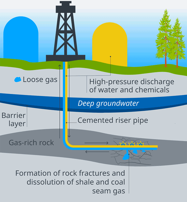
Fracking is a technique for increasing the permeability of rock so that oil, natural gas or geothermal energy can be extracted more easily...